XRP7708EVB Exar Corporation, XRP7708EVB Datasheet - Page 17
XRP7708EVB
Manufacturer Part Number
XRP7708EVB
Description
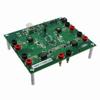
EVAL BOARD FOR XRP7708
Manufacturer
Exar Corporation
Type
PMIC Solutionsr
Specifications of XRP7708EVB
Main Purpose
DC/DC, Step Down
Outputs And Type
*
Voltage - Output
*
Current - Output
*
Voltage - Input
*
Regulator Topology
Buck
Frequency - Switching
*
Board Type
Fully Populated
Utilized Ic / Part
XRP7708
Board Size
6 mm x 6 mm x 0.8 mm
Interface Type
I2C
Maximum Operating Temperature
+ 125 C
Operating Supply Voltage
6.5 V to 20 V
Product
Power Management Development Tools
Sense Voltage (max)
5 mV
Dimensions
6 mm x 6 mm x 0.8 mm
Silicon Manufacturer
Exar
Silicon Core Number
XRP7708
Kit Application Type
Power Management - Voltage Regulator
Application Sub Type
Step Down DC/DC Controller
For Use With/related Products
XRP7708
Lead Free Status / RoHS Status
Lead free / RoHS Compliant
Power - Output
-
Lead Free Status / RoHS Status
Lead free / RoHS Compliant
Other names
1016-1346


The XRP7708 also offers an Over-Current warning flag. This warning flag resides in the
READ_OVC_FLAG register. The warning flag bit will be set when the output current gets to within a
specified value of the output current limit threshold enabling the host to reduce power
consumption. The SET_VIOUT_MAX_CHx register allows the warning flag threshold to be set 10mV,
20mV, 30mV or 40mV below VIOUT_MAX. The warning flag will be automatically cleared when the
current drops below the warning threshold.
When an over-current condition occurs, PWM drivers in the corresponding channels are disabled.
After a 200ms timeout, the controller is re-powered and soft-start is initiated. When the over-
current condition is reached the controller will check the SET_FAULT_RESP_CONFIG_LB and
SET_FAULT_RESP_CONFIG_HB to determine whether there are any “following” channels that need
to be similarly restarted. The controller will also set the fault flags in READ_OVC_FAULT_WARN
register.
Typically the over-current fault threshold would be set to 130-140% of the maximum desirable
output current. This will help avoid any over-current conditions caused by transients that would
shut down the output channel.
CHIP OPERATION AND CONFIGURATION
S
The SET_SS_RISE_CHx register is a 16 bit register which specifies the soft-start delay and the
ramp characteristics for a specific channel. This register allows the customer to program the
channel with a 250us step resolution and up to a maximum 16ms delay.
Bits [15:10] specify the delay after enabling a channel but before outputting pulses; where each bit
represents 250us steps. Bits [9:0] specify the rise time of the channel; these 10 bits define the
number of microseconds for each 50mV increment to reach the target voltage.
S
The SET_PD_FALL_CHx register is a 16 bit register. This register specifies the soft-stop delay and
ramp (fall-time) characteristics for when the chip receives a channel disable indication from the
Host to shutdown the channel.
Bits [15:10] specify the delay after disabling a channel but before starting the shutdown of the
channel; where each bit represents 250us steps. Bits [9:0] specify the fall time of the channel;
these 10 bits define the number of microseconds for each 50mV increment to reach the discharge
threshold.
© 2010 Exar Corporation
Over-Current Fault Handling
OFT
OFT
-S
-S
TART
TOP
Enable
Signal
Vout
Q
Q
Fig. 19: Channel POwer Up Sequence
u
u
a
a
d
d
C
C
Bit [15:10]
DELAY
h
h
a
a
17/27
n
n
n
n
SS_RISE_CHx
REGISTER
e
e
l
l
D
D
i
i
g
g
i
i
t
t
a
a
RISE TIME
Bit [9:0]
l
l
P
P
W
W
M
M
S
S
t
t
e
e
p
p
D
D
o
o
w
w
n
n
X
X
C
C
R
R
o
o
n
P
n
P
Rev. 1.0.3
t
t
7
7
r
r
o
7
o
7
l
l
0
0
l
l
e
e
8
8
r
r
Related parts for XRP7708EVB
Image
Part Number
Description
Manufacturer
Datasheet
Request
R

Part Number:
Description:
Quad Channel Digital Pwm Step Down Controller
Manufacturer:
Exar Corporation
Datasheet:
Part Number:
Description:
BiCMOS Fixed, Quad, Voltage Output, Single or Dual Supply 8-Bit Digital-to-Analog Converter
Manufacturer:
Exar Corporation
Datasheet:
Part Number:
Description:
Manufacturer:
Exar Corporation
Datasheet:
Part Number:
Description:
Voltage-Controlled Oscillator
Manufacturer:
Exar Corporation
Datasheet:
Part Number:
Description:
INTEGRATED LINE TRANSMITTER
Manufacturer:
Exar Corporation
Datasheet:
Part Number:
Description:
Monolithic Function Generator
Manufacturer:
Exar Corporation
Datasheet:
Part Number:
Description:
CMOS Microprocessor Compatible Double-Buffered 12-Bit Digital-to-Analog Converter
Manufacturer:
Exar Corporation
Datasheet:
Part Number:
Description:
CMOS 6 BIT HIGH SPEED ANALOG TO DIGITAL CONVERTER
Manufacturer:
Exar Corporation
Datasheet:
Part Number:
Description:
Manufacturer:
Exar Corporation
Datasheet:
Part Number:
Description:
Manufacturer:
Exar Corporation
Datasheet:
Part Number:
Description:
8-Channel, Voltage Output 10 MHz Input Bandwidth 8-Bit Multiplying DACs with Serial Digital Data Por
Manufacturer:
Exar Corporation
Datasheet:
Part Number:
Description:
15 V CMOS Multiplying10-Bit Digital-to-Analog Converter
Manufacturer:
Exar Corporation
Datasheet:
Part Number:
Description:
Monolithic Function Generator
Manufacturer:
Exar Corporation
Datasheet: