MCIMX53-START Freescale Semiconductor, MCIMX53-START Datasheet - Page 46
MCIMX53-START
Manufacturer Part Number
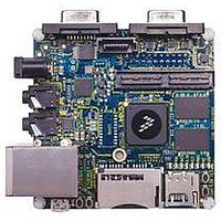
MCIMX53-START
Description
KIT DEVELOPMENT I.MX53
Manufacturer
Freescale Semiconductor
Series
i.MX53r
Type
MCUr
Datasheets
1.MCIMX53-START.pdf
(2 pages)
2.MCIMX53-START.pdf
(180 pages)
3.MCIMX53-START.pdf
(204 pages)
Specifications of MCIMX53-START
Contents
Board
Silicon Manufacturer
Freescale
Core Architecture
ARM
Core Sub-architecture
Cortex - A8
Silicon Core Number
I.MX5
Silicon Family Name
I.MX53
Peak Reflow Compatible (260 C)
Yes
Rohs Compliant
Yes
Leaded Process Compatible
Yes
Lead Free Status / RoHS Status
Lead free / RoHS Compliant
For Use With/related Products
i.MX53
Lead Free Status / Rohs Status
Supplier Unconfirmed
Available stocks
Company
Part Number
Manufacturer
Quantity
Price


1
2
3
Electrical Characteristics
46
Boot value NFC_FREQ_SEL Fuse High (burned)
Boot value NFC_FREQ_SEL Fuse Low
For RBB_MODE=1, using NANDF_RB0 signal for ready/busy indication. This mode require setting the delay line. See the
Reference Manual for details.
emi_slow_clk (MHz)
133
A potential limitation for minimum clock frequency may exist for some
devices. When the clock frequency is too low, the data bus capturing might
occur after the specified t
clock frequency above 25.6 MHz (that is, T = 39 ns) guaranties a proper
operation for devices having t
NFC_FREQ_SEL Fuse be set accordingly to initiate the boot with
33.33 MHz clock.
Lower frequency operation can be supported for most available devices in
the market, relying on data lines Bus-Keeper logic. This depends on device
behavior on the data bus in the time interval between data output valid to
data output high-Z state. In NAND device parameters this period is marked
between t
data transition from valid value to high-Z occurs without going through
other states. Setting the data bus pads to Bus-Keeper mode in the IOMUXC
registers, keeps the data bus valid internally after the specified hold time,
allowing proper capturing with slower clock.
NFCLE
NFCE_B
NFWE_B
NFIO[7:0]
i.MX53xA Automotive and Infotainment Applications Processors, Rev. 1
rhoh
Table 33. NFC Clock Settings Examples (continued)
nfc_podf (Division Factor)
and t
Figure 10. Command Latch Cycle Timing
rhz
(RE_B high to output high-Z). In most devices, the
NF1
4
3
2
rhoh
(RE_B high to output hold) period. Setting the
NF3
rhoh
command
NF8
NOTE
> 15 ns. It is also recommended that the
NF5
NF9
enfc_clk (MHz)
NF2
44.33
33.33
66
NF4
3
3
Freescale Semiconductor
T-Clock Period (ns)
22.5
30
15
Related parts for MCIMX53-START
Image
Part Number
Description
Manufacturer
Datasheet
Request
R

Part Number:
Description:
MCIMX-LVDS1
Manufacturer:
Freescale Semiconductor
Datasheet:

Part Number:
Description:
Manufacturer:
Freescale Semiconductor, Inc
Datasheet:
Part Number:
Description:
Manufacturer:
Freescale Semiconductor, Inc
Datasheet:
Part Number:
Description:
Manufacturer:
Freescale Semiconductor, Inc
Datasheet:
Part Number:
Description:
Manufacturer:
Freescale Semiconductor, Inc
Datasheet:
Part Number:
Description:
Manufacturer:
Freescale Semiconductor, Inc
Datasheet:
Part Number:
Description:
Manufacturer:
Freescale Semiconductor, Inc
Datasheet:
Part Number:
Description:
Manufacturer:
Freescale Semiconductor, Inc
Datasheet:
Part Number:
Description:
Manufacturer:
Freescale Semiconductor, Inc
Datasheet:
Part Number:
Description:
Manufacturer:
Freescale Semiconductor, Inc
Datasheet:
Part Number:
Description:
Manufacturer:
Freescale Semiconductor, Inc
Datasheet:
Part Number:
Description:
Manufacturer:
Freescale Semiconductor, Inc
Datasheet:
Part Number:
Description:
Manufacturer:
Freescale Semiconductor, Inc
Datasheet:
Part Number:
Description:
Manufacturer:
Freescale Semiconductor, Inc
Datasheet:
Part Number:
Description:
Manufacturer:
Freescale Semiconductor, Inc
Datasheet: