MCIMX53-START Freescale Semiconductor, MCIMX53-START Datasheet - Page 74
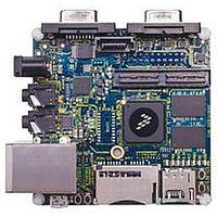
MCIMX53-START
Manufacturer Part Number
MCIMX53-START
Description
KIT DEVELOPMENT I.MX53
Manufacturer
Freescale Semiconductor
Series
i.MX53r
Type
MCUr
Datasheets
1.MCIMX53-START.pdf
(2 pages)
2.MCIMX53-START.pdf
(180 pages)
3.MCIMX53-START.pdf
(204 pages)
Specifications of MCIMX53-START
Contents
Board
Silicon Manufacturer
Freescale
Core Architecture
ARM
Core Sub-architecture
Cortex - A8
Silicon Core Number
I.MX5
Silicon Family Name
I.MX53
Peak Reflow Compatible (260 C)
Yes
Rohs Compliant
Yes
Leaded Process Compatible
Yes
Lead Free Status / RoHS Status
Lead free / RoHS Compliant
For Use With/related Products
i.MX53
Lead Free Status / Rohs Status
Supplier Unconfirmed
Available stocks
Company
Part Number
Manufacturer
Quantity
Price


1
2
Electrical Characteristics
4.7.5
This section describes the electrical information of the Fast Ethernet Controller (FEC) module. The FEC
is designed to support both 10 and 100 Mbps Ethernet/IEEE 802.3 networks. An external transceiver
interface and transceiver function are required to complete the interface to the media. The FEC supports
the 10/100 Mbps MII (18 pins in total) and the 10 Mbps (only 7-wire interface, which uses 7 of the MII
pins), for connection to an external Ethernet transceiver. For the pin list of MII and 7-wire, see the i.MX53
Reference Manual.
This section describes the AC timing specifications of the FEC. The MII signals are compatible with
transceivers operating at a voltage of 3.3 V.
4.7.5.1
The MII receive signal timing involves the FEC_RXD[3:0], FEC_RX_DV, FEC_RX_ER, and
FEC_RX_CLK signals. The receiver functions correctly up to a FEC_RX_CLK maximum frequency of
25 MHz + 1%. There is no minimum frequency requirement but the processor clock frequency must
exceed twice the FEC_RX_CLK frequency.
parameters and
74
.
FEC_RX_DV, FEC_RX_CLK, and FEC_RXD0 have same timing in 10 Mbps 7-wire interface mode.
Test conditions: 25pF on each output signal.
No.
SD3
SD4
M1
M2
M3
M4
ID
FEC_RXD[3:0], FEC_RX_DV, FEC_RX_ER to FEC_RX_CLK setup
FEC_RX_CLK to FEC_RXD[3:0], FEC_RX_DV, FEC_RX_ER hold
FEC_RX_CLK pulse width high
FEC_RX_CLK pulse width low
eSDHC Input Setup Time
eSDHC Input Hold Time
FEC AC Timing Parameters
MII Receive Signal Timing
Figure 36
i.MX53xA Automotive and Infotainment Applications Processors, Rev. 1
Table 47. eMMC4.4 Interface Timing Specification (continued)
shows MII receive signal timings.
Parameter
Characteristics
Table 48. MII Receive Signal Timing
1 2
Table 48
lists the MII receive channel signal timing
Symbols
t
ISU
t
IH
35%
35%
Min
5
5
Min
2.5
2.5
Max
65%
65%
—
—
Freescale Semiconductor
Max
FEC_RX_CLK period
FEC_RX_CLK period
—
—
Unit
ns
ns
Unit
ns
ns
Related parts for MCIMX53-START
Image
Part Number
Description
Manufacturer
Datasheet
Request
R

Part Number:
Description:
MCIMX-LVDS1
Manufacturer:
Freescale Semiconductor
Datasheet:

Part Number:
Description:
Manufacturer:
Freescale Semiconductor, Inc
Datasheet:
Part Number:
Description:
Manufacturer:
Freescale Semiconductor, Inc
Datasheet:
Part Number:
Description:
Manufacturer:
Freescale Semiconductor, Inc
Datasheet:
Part Number:
Description:
Manufacturer:
Freescale Semiconductor, Inc
Datasheet:
Part Number:
Description:
Manufacturer:
Freescale Semiconductor, Inc
Datasheet:
Part Number:
Description:
Manufacturer:
Freescale Semiconductor, Inc
Datasheet:
Part Number:
Description:
Manufacturer:
Freescale Semiconductor, Inc
Datasheet:
Part Number:
Description:
Manufacturer:
Freescale Semiconductor, Inc
Datasheet:
Part Number:
Description:
Manufacturer:
Freescale Semiconductor, Inc
Datasheet:
Part Number:
Description:
Manufacturer:
Freescale Semiconductor, Inc
Datasheet:
Part Number:
Description:
Manufacturer:
Freescale Semiconductor, Inc
Datasheet:
Part Number:
Description:
Manufacturer:
Freescale Semiconductor, Inc
Datasheet:
Part Number:
Description:
Manufacturer:
Freescale Semiconductor, Inc
Datasheet:
Part Number:
Description:
Manufacturer:
Freescale Semiconductor, Inc
Datasheet: