Z7.282.0027.0 WIELAND ELECTRIC, Z7.282.0027.0 Datasheet - Page 413
Z7.282.0027.0
Manufacturer Part Number
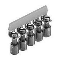
Z7.282.0027.0
Description
TERMINAL BLOCK JUMPER BAR, 40WAY, 8MM
Manufacturer
WIELAND ELECTRIC
Series
WK6r
Datasheet
1.07.311.0155.0.pdf
(900 pages)
Specifications of Z7.282.0027.0
Accessory Type
Jumper
No. Of Positions
40
Pitch Spacing
8mm
Row Pitch
8mm
For Use With
Wieland WK6/U Series DIN Rail Mount Terminal Blocks
Lead Free Status / RoHS Status
Lead free / RoHS Compliant


ricos
Dimensions (mm): W x H x D
74 x 92 x 51
Specifications are subject to change without notice
Description
Buscoupler with diagnosis function
Mode display:
Wiring diagrams, derating curves
System data
Max. number of nodes
Transmission medium
Max. network expansion
Baud rate
Internal bus refresh
Bus connection
Technical information
Max. number of I/O bytes
Number of I/O modules per node
Number of digital I/O points per node
Number of analog I/O points per node
Address setting (MAC ID)
Stet
Operating voltage
Current input
Insulation voltage
Creepage distances and clearances
Electrostatic discharge
Electromagnetic fields
Immunity / emitted interference
Burst
Connection style
Cross-sectional area-fine stranded / solid
Ambient temperature
Storage temperature
Bus-specific status display
Accessories
Bus connector
Manual, German
Manual, English
EDS file and Word template for labels
Marking tag, 8-digit, unmarked
Marking tag, 8-digit, marked (upon request)
End clamp for DIN rail
Modular buscoupler
DeviceNet
A
Type
BC-DEVICENET
incl. 1 busconnector
FORCE mode: LED yellow
TRIGGER mode: LED yellow
LOCK mode: LED yellow
STOP mode: LED yellow
RUN mode: LED green
see page 430
64 with repeater
screened copper cable trunk line AWG 15, 18
screened copper cable drop line AWG 22, 24
100 m – 500 m (depending on baud rate / cable)
125/250/500 kBaud (setting via keyboard)
2 ms
5pole connector, screw
64 E-Byte/64 A-Byte
8
128
32
1...63 (via keyboard)
PC or PLC
24 V DC, ± 20 %, max. 5 % residual ripple
< 125 mA (at 24 V and without I/O modules)
< 500 mA (at 24 V with I/O modules)
350 V AC, 50 Hz (system/supply)
DIN EN 61131-2; DIN EN 50178
EN 61000-4-2; 8 KV air; 4 KV contact
ENV 50140; 10 V/m; 30...1000 MHz
EN 61000-6-2/EN 55011, limit value class A, group 1
2 kV accord. to DIN EN 61000-4-4
spring connection
26 – 14 AWG / 26 – 16 AWG
0 °C...+ 55 °C (accord. to DIN 40040)
– 25 °C...+ 75 °C (accord. to DIN 40040)
RUN
status to master
ready for operation
operating voltage
25.323.3501.0
05.591.3389.0
05.562.1389.0
05.591.3255.0
04.242.1553.0
Z5.522.8553.0
; Approvals:
E
Part no.
83.032.0000.1
LED green
LED green/red
LED green/red
LED green
Std. pack
1
MOD
RUN
NET
5 V
Modular buscoupler
CANopen
A
Type
BC-CANOPEN
incl. 1 busconnector
FORCE mode: LED yellow
TRIGGER mode: LED yellow
LOCK mode: LED yellow
STOP mode: LED yellow
RUN mode: LED green
see page 430
256
screened copper cable 3 x 0.25 mm
100 m – 500 m (depending on baud rate / cable)
10 kBaud...1 MBaud (setting via keyboard)
2 ms
5pole connector, screw
9 R-PDOs; 9 T-PDOs
6
96
24
1...126 (via keyboard)
PC or PLC
24 V DC, ± 20 %, max. 5 % residual ripple
< 125 mA (at 24 V and without I/O modules)
< 500 mA (at 24 V with I/O modules)
350 V AC, 50 Hz (system / supply)
DIN EN 61131-2; DIN EN 50178
EN 61000-4-2; 8 KV air; 4 KV contact
ENV 50140; 10 V/m; 30...1000 MHz
EN 61000-6-2/EN 55011, limit value class A, group 1
2 kV accord. to DIN EN 61000-4-4
spring connection
26 – 14 AWG / 26 – 16 AWG
0 °C...+ 55 °C (accord. to DIN 40040)
–25 °C...+ 75 °C (accord. to DIN 40040)
RUN
network status
module status
operating voltage
25.323.3501.0
05.591.3389.0
05.562.1389.0
05.591.3255.0
04.242.1553.0
Z5.522.8553.0
; Approvals:
E
Part no.
83.033.0000.1
LED green
LED green/red
LED green/red
LED green
in preparation
2
/AWG 23
Std. pack
1
MOD
RUN
NET
411
5 V
Related parts for Z7.282.0027.0
Image
Part Number
Description
Manufacturer
Datasheet
Request
R


Part Number:
Description:
End Plate
Manufacturer:
WIELAND ELECTRIC
Datasheet:

Part Number:
Description:
END PLATE, WK SERIES TERMINAL BLOCK
Manufacturer:
WIELAND ELECTRIC
Datasheet:
Part Number:
Description:
END PLATE, WK/WKN SERIES TERMINAL BLOCK
Manufacturer:
WIELAND ELECTRIC
Datasheet:

Part Number:
Description:
PARTITION PLATE WK SERIES TERMINAL BLOCK
Manufacturer:
WIELAND ELECTRIC
Datasheet: