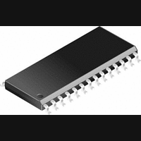
CS8420-CS Cirrus Logic Inc, CS8420-CS Datasheet - Page 76

CS8420-CS
Manufacturer Part Number
CS8420-CS
Description
Transceiver IC
Manufacturer
Cirrus Logic Inc
Datasheet
1.CS8420-CS.pdf
(80 pages)
Specifications of CS8420-CS
Audio Control Type
Sample Rate Converter
Supply Voltage Range
4.75V To 5.25V
Operating Temperature Range
-10°C To +70°C
Audio Ic Case Style
SOIC
No. Of Pins
28
Msl
MSL 2 - 1 Year
Frequency Max
108GHz
Bandwidth
20kHz
Rohs Compliant
No
Lead Free Status / RoHS Status
Contains lead / RoHS non-compliant
Available stocks
Company
Part Number
Manufacturer
Quantity
Price
Company:
Part Number:
CS8420-CS
Manufacturer:
CRY
Quantity:
5 510
Company:
Part Number:
CS8420-CS
Manufacturer:
CIRRUS
Quantity:
225
Part Number:
CS8420-CS
Manufacturer:
CRYSTAL
Quantity:
20 000
Company:
Part Number:
CS8420-CS*
Manufacturer:
NEC
Quantity:
700
Company:
Part Number:
CS8420-CSZ
Manufacturer:
CIRRUS
Quantity:
319
Company:
Part Number:
CS8420-CSZ
Manufacturer:
CIRRUS
Quantity:
9 908
Part Number:
CS8420-CSZ
Manufacturer:
CIRRUS
Quantity:
20 000
becoming completely full, allowing incoming data
to overwrite data that has not yet been output
through the AES3 transmitter.
16.2.4 Mode (3): Reserved
This mode has been removed. Use IEC Consumer
mode B.
16.2.5 Mode (4): IEC Consumer B
In this mode, the partitioning problem is solved by
buffering an entire message before starting to trans-
mit it. In this scheme, zero-segments between mes-
sages will be expanded when Fso > Fsi, but the
integrity of individual messages is preserved.
The overwriting problem (when Fso < Fsi) is
solved by only storing a portion of the input U data
in the FIFO. Specifically, only the IUs themselves
are stored (and not the zeroes that provide inter-IU
and inter-message “filler”). An inter-IU filler seg-
ment of fixed length (OF) will be added back to the
messages at the FIFO output, where the length of
OF is equal to the shortest observed input filler seg-
ment (IF).
Storing only IUs (and not filler) within the FIFO
makes it possible for the slower AES3 transmitter
to “catch up” to the faster AES3 receiver as data is
read out of the FIFO. This is because nothing is
written into the FIFO when long strings of zeroes
are input to the AES-EBU receiver. During this
time of no writing, the transmitter can read out data
that had previously accumulated, allowing the
FIFO to empty out. If the FIFO becomes complete-
76
ly empty, zeroes are transmitted until a complete
message is written into the FIFO.
Mode 4 is not fail-safe; the FIFO can still get com-
pletely full if there isn't enough “zero-padding” be-
tween incoming messages. It is up to the user to
provide proper padding, as defined below:
Minimum padding
= (Fsi/Fso - 1)*[8N + (N-1)*IF +9] + 9
where N is the number of IUs in the message, IF is
the number of filler bits between each IU, and Fso
Example 1: Fsi/Fso = 2, N=4, IF=1: minimum
proper padding is 53 bits.
Example 2: Fsi/Fso = 1, N=4, IF=7: min proper
padding is 9 bits.
The CS8420 detects when an overwrite has oc-
curred in the FIFO, and synchronously resets the
entire FIFO structure to prevent corrupted U data
from being merged into the transmitted AES3 data
stream. The CS8420 can be configured to generate
an interrupt when this occurs.
Mode 4 is recommended for properly formatted U
data where mode 3 cannot provide acceptable per-
formance, either because of a too-extreme Fsi/Fso
ratio, or because it's unacceptable to change the
lengths of filler segments. Mode 4 provides error-
free performance over the complete range of
Fsi/Fso ratios (provided that the input messages are
properly zero-padded for Fsi > Fso).
Fsi.
CS8420
DS245PP2


