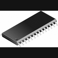
DS92LV1212AMSA National Semiconductor, DS92LV1212AMSA Datasheet - Page 3

DS92LV1212AMSA
Manufacturer Part Number
DS92LV1212AMSA
Description
IC, DESERIALIZER, 40MHZ, 10BIT, SSOP-28
Manufacturer
National Semiconductor
Datasheet
1.DS92LV1212AMSA.pdf
(15 pages)
Specifications of DS92LV1212AMSA
Serdes Function
Deserializer
Data Rate
400Mbps
Ic Output Type
LVTTL
No. Of Inputs
1
No. Of Outputs
10
Supply Voltage Range
3V To 3.6V
Driver Case Style
SSOP
No. Of Pins
28
Lead Free Status / RoHS Status
Contains lead / RoHS non-compliant
Available stocks
Company
Part Number
Manufacturer
Quantity
Price
Company:
Part Number:
DS92LV1212AMSA
Manufacturer:
national
Quantity:
286
Company:
Part Number:
DS92LV1212AMSA
Manufacturer:
NSC
Quantity:
11
Company:
Part Number:
DS92LV1212AMSA-NOPB
Manufacturer:
NSC
Quantity:
56
Company:
Part Number:
DS92LV1212AMSA/NOPB
Manufacturer:
TI
Quantity:
1 900
Part Number:
DS92LV1212AMSAX
Manufacturer:
NS/国半
Quantity:
20 000
Company:
Part Number:
DS92LV1212AMSAX/NOPB
Manufacturer:
TI
Quantity:
1 900
Part Number:
DS92LV1212AMSAX/NOPB
Manufacturer:
TI/德州仪器
Quantity:
20 000
Resynchronization
recommendation is to provide a feedback loop using the
LOCK pin itself to control the sync request of the Serializer
(SYNC1 or SYNC2). Dual SYNC pins are provided for mul-
tiple control in a multi-drop application. Sending sync pat-
terns for resynchronization is desirable when lock times
within a specific time are critical. However, the Deserializer
can lock to random data, which is discussed in the next
section.
Random Lock Initialization and
Resynchronization
The initialization and resynchronization methods described
in their respective sections are the fastest ways to establish
the link between the Serializer and Deserializer. However,
the DS92LV1212A can attain lock to a data stream without
requiring the Serializer to send special SYNC patterns. This
allows the DS92LV1212A to operate in “open-loop” applica-
tions. Equally important is the Deserializer’s ability to support
hot insertion into a running backplane. In the open loop or
hot insertion case, we assume the data stream is essentially
random. Therefore, because lock time varies due to data
stream characteristics, we cannot possibly predict exact lock
time. The primary constraint on “random” lock time is the
initial phase relation between the incoming data and the
REFCLK when the Deserializer powers up. As described in
the next paragraph, the data contained in the data stream
can also affect lock time.
If a specific pattern is repetitive, the Deserializer could enter
“false lock” - falsely recognizing the data pattern as the
clocking bits. We refer to such a pattern as a repetitive
multi-transition, RMT. This occurs when more than one
Low-High transition takes place in a clock cycle over multiple
cycles. This occurs when any bit, except DIN 9, is held at a
low state and the adjacent bit is held high, creating a 0-1
transition. In the worst case, the Deserializer could become
locked to the data pattern rather than the clock. Circuitry
within the DS92LV1212A can detect that the possibility of
“false lock” exists. The circuitry accomplishes this by detect-
ing more than one potential position for clocking bits. Upon
detection, the circuitry will prevent the LOCK output from
becoming active until the potential “false lock” pattern
changes. The false lock detect circuitry expects the data will
eventually change, causing the Deserializer to lose lock to
the data pattern and then continue searching for clock bits in
the serial data stream. Graphical representations of RMT are
shown on the following page. Please note that RMT only
applies to bits DIN0-DIN8.
(Continued)
3
Powerdown
When no data transfer occurs, you can use the Powerdown
state. The Serializer and Deserializer use the Powerdown
state, a low power sleep mode, to reduce power consump-
tion. The Deserializer enters Powerdown when you drive
PWRDN and REN low. The Serializer enters Powerdown
when you drive PWRDN low. In Powerdown, the PLL stops
and the outputs enterTRI-STATE, which disables load cur-
rent and reduces supply current to the milliampere range. To
exit Powerdown, you must drive the PWRDN pin high.
Before valid data exchanges between the Serializer and
Deserializer, you must reinitialize and resynchronize the de-
vices to each other. Initialization of the Serializer takes 510
TCLK cycles. The Deserializer will initialize and assert LOCK
high until lock to the Bus LVDS clock occurs.
TRI-STATE
The Serializer enters TRI-STATE when the DEN pin is driven
low. This puts both driver output pins (DO+ and DO−) into
TRI-STATE. When you drive DEN high, the Serializer returns
to the previous state, as long as all other control pins remain
static (SYNC1, SYNC2, PWRDN, TCLK_R/F).
When you drive the REN pin low, the Deserializer enters
TRI-STATE.
(ROUT0–ROUT9) and RCLK will enter TRI-STATE. The
LOCK output remains active, reflecting the state of the PLL.
Consequently,
the
receiver
output
www.national.com
pins


