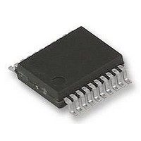
74HCT241PW NXP Semiconductors, 74HCT241PW Datasheet - Page 6

74HCT241PW
Manufacturer Part Number
74HCT241PW
Description
IC, LOGIC, 74HCT, BUFFER, TSSOP20
Manufacturer
NXP Semiconductors
Datasheet
1.74HCT241D.pdf
(8 pages)
Specifications of 74HCT241PW
Supply Voltage Range
4.5V To 5.5V
Logic Case Style
TSSOP
No. Of Pins
20
Operating Temperature Range
-40°C To +125°C
Svhc
No SVHC (18-Jun-2010)
Logic Ic Base Number
74241
Package / Case
TSSOP
Logic Device Type
Buffer / Line Driver, Non Inverting
Rohs Compliant
Yes
Lead Free Status / RoHS Status
Lead free / RoHS Compliant
Philips Semiconductors
DC CHARACTERISTICS FOR 74HCT
For the DC characteristics see
Output capability: bus driver
I
Note to HCT types
The value of additional quiescent supply current ( I
To determine I
AC CHARACTERISTICS FOR 74HCT
GND = 0 V; t
September 1993
CC
INPUT
1A
2A
1OE
2OE
SYMBOL PARAMETER
t
t
t
t
PHL
PZH
PHZ
THL
Octal buffer/line driver; 3-state
n
n
category: MSI
/ t
/ t
/ t
/ t
TLH
PLH
PZL
PLZ
UNIT LOAD COEFFICIENT
0.70
0.70
0.70
1.50
propagation delay
3-state output enable time
3-state output disable time
output transition time
r
= t
1A
2A
1OE to 1Y
2OE to 2Y
1OE to 1Y
2OE to 2Y
CC
f
n
n
= 6 ns; C
to 1Y
to 2Y
per input, multiply this value by the unit load coefficient shown in the table below.
n
n
n
n
n
n
;
;
;
L
= 50 pF
“74HC/HCT/HCU/HCMOS Logic Family Specifications”
min. typ. max. min. max.
13
15
18
5
25
CC
22
30
30
12
) for a unit load of 1 is given in the family specifications.
6
T
74HCT
amb
40 to 85
( C)
28
38
38
15
min.
40 to 125
33
45
45
18
max.
.
ns
ns
ns
ns
UNIT
74HC/HCT241
4.5
4.5
4.5
4.5
V
(V)
TEST CONDITIONS
CC
Product specification
Fig.5
Fig.6
Fig.6
Fig.5
WAVEFORMS


