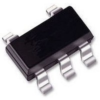
XC9236A33DMR Torex Semiconductor Ltd, XC9236A33DMR Datasheet - Page 14

XC9236A33DMR
Manufacturer Part Number
XC9236A33DMR
Description
IC, DCDC SYNCH BUCK 3MHZ 3.3V SOT25
Manufacturer
Torex Semiconductor Ltd
Datasheet
1.XC9236A18DMR.pdf
(33 pages)
Specifications of XC9236A33DMR
Primary Input Voltage
6V
No. Of Outputs
1
Output Voltage
3.3V
Output Current
600mA
Voltage Regulator Case Style
SOT-25
No. Of Pins
5
Operating Temperature Range
-40°C To +85°C
Svhc
No SVHC
Lead Free Status / RoHS Status
Lead free / RoHS Compliant
Available stocks
Company
Part Number
Manufacturer
Quantity
Price
Part Number:
XC9236A33DMR-G
Manufacturer:
TOREX
Quantity:
20 000
14/33
■OPERATIONAL DESCRIPTION (Continued)
<Short-Circuit Protection>
The short-circuit protection circuit monitors the internal R1 and R2 divider voltage from the V
the block diagram shown in the previous page). In case where output is accidentally shorted to the Ground and when
the FB point voltage decreases less than half of the reference voltage (Vref) and a current more than the I
the Pch MOS driver transistor, the short-circuit protection quickly operates to turn off and to latch the driver transistor.
For the D/E/F/G series, it does not matter how much the current limit, once the FB voltage become less than the
quarter of reference voltage (V
latch mode, the operation can be resumed by either turning the IC off and on via the CE/MODE pin, or by restoring
power supply to the V
When sharp load transient happens, a voltage drop at the V
short circuit protection may operate in the voltage higher than 1/2 V
<UVLO Circuit>
When the V
prevent false pulse output caused by unstable operation of the internal circuitry. When the V
or higher, switching operation takes place. By releasing the UVLO function, the IC performs the soft start function to
initiate output startup operation. The soft start function operates even when the V
the UVLO operating voltage. The UVLO circuit does not cause a complete shutdown of the IC, but causes pulse output to
be suspended; therefore, the internal circuitry remains in operation.
<PFM Switch Current>
In PFM control operation, until coil current reaches to a specified level (I
on. In this case, time that the Pch MOS driver transistor is kept on (TON) can be given by the following formula.
TON= L
< PFM Duty Limit >
In PFM control operation, the PFM duty limit (
duty increases (e.g. the condition that the step-down ratio is small), it’s possible for Pch MOS driver transistor to be turned
off even when coil current doesn’t reach to I
XC9235/XC9236/XC9237
I Lx
Lx
×
I
PFM
IN
pin voltage becomes 1.4V or lower, the Pch MOS driver transistor output driver transistor is forced OFF to
図 IPFM ①
/ (V
Ton
IN
−
IN
V
pin.
OUT
)
REF
→I
), the short-circuit protection operates to latch the Pch MOS driver transistor. In
PFM
①
0mA
PFM
I
PFM
DTY
.
Series
LIMIT_PFM
→I
PFM
) is set to 200% (TYP.). Therefore, under the condition that the
②
OUT
is propagated to the FB point through C
I Lx
Lx
OUT
voltage.
PFM
), the IC keeps the Pch MOS driver transistor
図 IPFM ②
PFM Duty Limit
FOSC
PFMデューティ制限
IN
pin voltage falls momentarily below
OUT
IN
pin (refer to FB point in
pin voltage becomes 1.8V
FB
, as a result,
0mA
I
LIM
PFM
flows to


