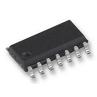
UCC35701D UNITRODE, UCC35701D Datasheet - Page 5

UCC35701D
Manufacturer Part Number
UCC35701D
Description
PWM CONTROLLER, SMD, 35701, SOIC14
Manufacturer
UNITRODE
Datasheet
1.UCC35701D.pdf
(23 pages)
Specifications of UCC35701D
Input Voltage
11V
Output Voltage
1V
Output Current
100mA
Frequency
700kHz
Supply Voltage Range
10V To 13V
Digital Ic Case Style
SOIC
No. Of Pins
14
Operating Temperature Range
0°C To +70°C
Available stocks
Company
Part Number
Manufacturer
Quantity
Price
Company:
Part Number:
UCC35701D
Manufacturer:
SIPEX
Quantity:
6 781
Part Number:
UCC35701D
Manufacturer:
UC
Quantity:
20 000
PIN DESCRIPTIONS (cont.)
VSCLAMP: Voltage at this pin is compared to the CT
voltage, providing a constant volt-second limit. The com-
parator output terminates the PWM pulse when the ramp
voltage exceeds VSCLAMP. The maximum on time is
given by:
The maximum duty cycle limit is given by:
FB: Input to the PWM comparator. This pin is intended
to be driven with an optocoupler circuit. Input impedance
is 50kW Typical modulation range is 1.6V to 3.6V.
SYNC: Level sensitive oscillator sync input. A high level
forces the gate drive output low and resets the ramp ca-
pacitor. On-time starts at the negative edge the pulse.
There is a 3mA pull down current on the pin, allowing it to
be disconnected when not used.
VREF: 5.0V trimmed reference with 2% variation over
line, load and temperature. Bypass with a minimum of
0.1mF to ground.
SS: Soft Start pin. A capacitor is connected between this
pin and ground to set the start up time of the converter.
After power up (V
fault condition has been cleared, the soft start capacitor
is charged to V
APPLICATION INFORMATION
(Note: Refer to the Typical Application Diagram on the first
page of this datasheet for external component names.) All the
equations given below should be considered as first order ap-
proximations with final values determined empirically for a spe-
cific application.
Power Sequencing
V
(R6) to the input line, with an additional path (R7) to a
low voltage bootstrap winding on the power transformer.
VFF is connected through a divider (R1/R2) to the input
line.
For circuit activation, all of the following conditions are
required:
1. VFF between 0.6V and 4.0V (operational input voltage
range).
2. VDD has been under the UVLO stop threshold to reset
the shutdown latch.
3. VDD is over the UVLO start threshold.
DD
t
D
ON
is normally connected through a high impedance
MAX
=
V
=
VS CLAMP
t
ON
T
2
·
=
I
REF
R T
V
DD
VS CLAMP
·
CT
V
by a nominal 18mA internal current
>13V AND V
R T
REF
>4.5V), or after a
5
source. While the soft start capacitor is charging, and
while V
output voltage of the converter is determined by the soft
start circuitry.
At High Line or Low Line fault conditions, the soft start
capacitor is discharged with a controlled discharge cur-
rent of about 500mA. During the discharge time, the duty
cycle of the converter is gradually decreased to zero.
This soft stop feature allows the synchronous rectifiers to
gradually discharge the output LC filter. An abrupt shut
off can cause the LC filter to oscillate, producing unpre-
dictable output voltage levels.
All other fault conditions (UVLO, VREF Low, Over Cur-
rent (0.6V on ILIM) or COUNT) will cause an immediate
stop of the converter. Furthermore, both the Over Current
fault and the COUNT fault will be internally latched until
V
threshold at the input of the Low Line comparator.
After all fault conditions are cleared and the soft start ca-
pacitor is discharged below 200 mV, a soft start cycle will
be initiated to restart the converter.
ILIM: Provides a pulse by pulse current limit by terminat-
ing the PWM pulse when the input is above 200mV. An
input over 600mV initiates a latched soft stop cycle.
COUNT: Capacitor to ground integrates current pulses
generated when ILIM exceeds 200mV.
ground sets the discharge time constant. A voltage over
4V will initiate a latched soft stop cycle.
The circuit will start at this point. I
the start up value of 130mA to the run value of 750mA.
The capacitor on SS is charged with a 18mA current.
When the voltage on SS is greater than 0.8V, output
pulses can begin, and supply current will increase to a
level determined by the MOSFET gate charge require-
ments to I
tive, the bootstrap winding should be sourcing the supply
current. If VDD falls below the UVLO stop threshold, the
controller will enter a shutdown sequence and turn the
controller off, returning the start sequence to the initial
condition.
VDD Clamp
An internal shunt regulator clamps VDD so the voltage
does not exceed a nominal value of 14V. If the regulator
is active, supply current must be limited to less than
20mA.
DD
drops below 9V or V
SS
< (0.4
VDD
~ 1mA + QT · fs. When the output is ac-
V
FB )
, the duty cycle, and therefore the
FF
goes below the 600mV
VDD
will increase from
UCC15701/2
UCC25701/2
UCC35701/2
A resistor to


