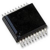
AS5134-ASSU austriamicrosystems, AS5134-ASSU Datasheet - Page 16

AS5134-ASSU
Manufacturer Part Number
AS5134-ASSU
Description
ENCODER, MAGNETIC, ROTARY, 8BIT, 20SSOP
Manufacturer
austriamicrosystems
Datasheet
1.AS5134-ASSU.pdf
(39 pages)
Specifications of AS5134-ASSU
Brief Features
9-Bit Multiturn Counter, User Programmable Zero Position And Sensitivity
Supply Voltage Range
4.5V To 5.5V
Operating Temperature Range
-40°C To +140°C
Digital Ic Case
RoHS Compliant
Ic Function
Programmable High Speed Magnetic Rotary Encoder
Rohs Compliant
Yes
AS5134
Data Sheet - D e t a i l e d D e s c r i p t i o n
Table 8. Programming Options for the Commutation Signals U/V/W
Daisy Chain Mode
The angle information from the device and the setup for the device is handled over the digital interface. A special port
(Dx) can be used to implement a daisy chain mode. Depending on the configuration, it is possible to implement a two
wire or a three wire mode. In the three wire mode, each communication starts with the rising edge of the chip select
signal. The Port Dx is used to transfer the chip select information from one device to the next. Refer to
Figure
clock source available for a certain time. The synchronization between the internal free running analog clock oscillator
and the external used digital clock source for the digital interface is done in a way that the digital clock frequency can
vary in a wide range.
Remark: Reset for the digital interface:
3 wire mode → via chip select
2 wire mode → via timeout
www.austriamicrosystems.com
chip select
DCLK
bidirectional data input
output
Daisy Chain Port
0
0
0
0
1
1
1
13. In the two wire interface mode, a timeout logic ensures that the digital interface will be reset if there is no
Port
uvw (11:9)
0
0
1
1
0
0
1
Symbol
0
1
0
1
0
1
1
DCLK
DIO
CS
Dx
BLDC Pole Pairs : 1 → electrical angle of 60º := mechanical angle: 60º
BLDC Pole Pairs : 2 → electrical angle of 60º := mechanical angle: 30º
BLDC Pole Pairs : 3 → electrical angle of 60º := mechanical angle: 20º
BLDC Pole Pairs : 4 → electrical angle of 60º := mechanical angle: 15º
BLDC Pole Pairs : 5 → electrical angle of 60º := mechanical angle: 12º
BLDC Pole Pairs : 6 → electrical angle of 60º := mechanical angle: 10º
Indicates the start of a new access cycle to the device
CS = LO → reset of the digital interface.
Clock source for the communication over the digital interface. The
maximum and minimum frequency depends on the mode.
Command and data information over one single line. The first bit of
the command defines a read or write access.
This port enables the daisy chain configuration of several devices.
Three wire mode: Indicates the end of an interface cycle. Dx can be
used as the chip select signal for the next device in the chain.
Two wire mode: Will be set with the first falling edge of DCLK and
hence, indicates a running clock; it will be cleared at the end of the
command sequence or after a timeout phase. Dx can be used as a
chip select signal in the two wire mode.
Revision 1.8
off → LO pad U,V,W, PWM
Function
Function
Figure 12
16 - 39
and


