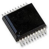
AS5134-ASSU austriamicrosystems, AS5134-ASSU Datasheet - Page 29

AS5134-ASSU
Manufacturer Part Number
AS5134-ASSU
Description
ENCODER, MAGNETIC, ROTARY, 8BIT, 20SSOP
Manufacturer
austriamicrosystems
Datasheet
1.AS5134-ASSU.pdf
(39 pages)
Specifications of AS5134-ASSU
Brief Features
9-Bit Multiturn Counter, User Programmable Zero Position And Sensitivity
Supply Voltage Range
4.5V To 5.5V
Operating Temperature Range
-40°C To +140°C
Digital Ic Case
RoHS Compliant
Ic Function
Programmable High Speed Magnetic Rotary Encoder
Rohs Compliant
Yes
AS5134
Data Sheet - D e t a i l e d D e s c r i p t i o n
Axial Distance (Airgap)
Figure 21. Sinusoidal Magnetic Field generated by the Rotating Magnet
The recommended magnetic field, measured at the chip surface on a radius equal to the Hall sensor array radius (typ.
1.1mm) should be within a certain range. This range lies between 45 and 75mT or between 20 and 80mT, depending
on the encoder product.
Linear position sensors are more sensitive as they use weaker magnets. The allowed magnetic range lies typically
between 5 and 60mT.
Angle Error vs. Radial and Axial Misalignment
The angle error is the deviation of the actual angle vs. the angle measured by the encoder. There are several factors in
the chip itself that contribute to this error, mainly offset and gain matching of the amplifiers in the analog signal path. On
the other hand, there is the nonlinearity of the signals coming from the Hall sensors, caused by misalignment of the
magnet and imperfections in the magnetic material.
Ideally, the Hall sensor signals should be sinusoidal, with equal peak amplitude of each signal. This can be maintained,
as long as all Hall elements are within the linear range of the magnetic field Bz
Accuracy
Accuracy is defined as the error between the measured angle and the actual angle. It is influenced by several factors:
Misalignment of the magnet further reduces the accuracy.
linearity over XY-misalignment. The center of the square XY-area corresponds to a centered magnet. The X- and Y-
axis extends to a misalignment of ±1mm in both directions. The total misalignment area of the graph covers a square
of 2x2 mm (79x79mil) with a step size of 200µm. The gap between surface and magnet is z=500µm.
www.austriamicrosystems.com
the non-linearity of the analog-digital converters
internal gain and mismatch errors
non-linearity due to misalignment of the magnet
vertical
field
B
0
Revision 1.8
Figure 22
shows an example of a 3D-graph displaying non-
(see Figure
360º
19).
29 - 39


