ADIS16405/PCBZ Analog Devices Inc, ADIS16405/PCBZ Datasheet - Page 13
ADIS16405/PCBZ
Manufacturer Part Number
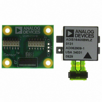
ADIS16405/PCBZ
Description
ADIS16405/PCB EVAL. BD. PB Free
Manufacturer
Analog Devices Inc
Series
iMEMS®, iSensor™r
Specifications of ADIS16405/PCBZ
Sensor Type
Accelerometer, Gyroscope, Magnetometer, 3 Axis
Sensing Range
±18g, ±75°/sec, ±150°/sec, ±300°/sec, ±2.5gauss
Interface
SPI Serial
Sensitivity
3.33mg/LSB, 0.0125 ~ 0.05°/sec/LSB, 0.5mgauss/LSB
Voltage - Supply
4.75 V ~ 5.25 V
Embedded
No
Utilized Ic / Part
ADIS16405
Silicon Manufacturer
Analog Devices
Silicon Core Number
ADIS16405
Kit Contents
Board
Rohs Compliant
Yes
Lead Free Status / RoHS Status
Lead free / RoHS Compliant
Lead Free Status / RoHS Status
Lead free / RoHS Compliant, Lead free / RoHS Compliant
Available stocks
Company
Part Number
Manufacturer
Quantity
Price
Company:

Part Number:
ADIS16405/PCBZ
Manufacturer:
GAMMA
Quantity:
4 600
Company:
Part Number:
ADIS16405/PCBZ
Manufacturer:
Analog Devices Inc
Quantity:
135


SENS_AVG[2:0] = 110 sets each stage tap to 64. The total
number of taps in the filter is equal to 2N + 1.
Dynamic Range
There are three dynamic range settings for the gyroscope: ±75°/sec,
±150°/sec, and ±300°/sec. The lower dynamic range settings
(±75°/sec and ±150°/sec) limit the minimum filter tap sizes to
maintain the resolution as the measurement range decreases.
The recommended order for programming the SENS_AVG
register is upper byte (sensitivity), followed by lower byte
(filtering). For example, set SENS_AVG[10:8] = 010 (DIN =
0xB902) for a measurement range of ±150°/sec, and then set
SENS_AVG[2:0] = 110 ( DIN = 0xB806) for 64 taps per stage
(129 taps overall).
Table 17. SENS_AVG
Bits
[15:11]
[10:8]
[7:3]
[2:0]
INPUT/OUTPUT FUNCTIONS
General-Purpose I/O
DIO1, DIO2, DIO3, and DIO4 are configurable, general-
purpose I/O lines that serve multiple purposes according to the
following control register priority: MSC_CTRL, ALM_CTRL,
and GPIO_CTRL. For example, set GPIO_CTRL = 0x080C
(DIN = 0xB508, and then 0xB40C) to set DIO1 and DIO2 as
inputs and DIO3 and DIO4 as outputs, with DIO3 set low and
DIO4 set high.
–100
–120
–140
–20
–40
–60
–80
0.001
0
Figure 15. Bartlett Window FIR Frequency Response
Settings
100
010
001
N = 2
N = 4
N = 16
N = 64
0.01
Description
Not used
Measurement range (sensitivity) selection
±300°/sec (default condition)
±150°/sec, filter taps ≥ 4 (Bits[2:0] ≥ 0x02)
±75°/sec, filter taps ≥ 16 (Bits[2:0] ≥ 0x04)
Not used
Number of taps in each stage N = 2
(Phase = N Samples)
FREQUENCY (
f
/
f
S
)
0.1
1
M
Rev. 0 | Page 13 of 16
Table 18. GPIO_CTRL
Bits
[15:12]
[11]
[10]
[9]
[8]
[7:4]
[3]
[2]
[1]
[0]
Input Clock Configuration
The input clock allows for external control over sampling in the
ADIS16405. Set GPIO_CTRL[3] = 0 (DIN = 0x0B200) and
SMPL_PRD[7:0] = 0x00 (DIN = 0xB600) to enable this function.
See Table 2 and Figure 4 for timing information.
Data Ready I/O Indicator
The factory default sets DIO1 as a positive data ready indicator
signal. The MSC_CTRL[2:0] register provides configuration
options for changing this. For example, set MSC_CTRL[2:0] =
100 (DIN = 0xB404) to change the polarity of the data ready
signal for interrupt inputs that require negative logic inputs for
activation. The pulse width will be between 100 μs and 200 μs
over all conditions.
Table 19. MSC_CTRL
Bits
[15:12]
[11]
[10]
[9]
[8]
[7]
[6]
[5:3]
[2]
[1]
[0]
General-Purpose I/O Line 2 (DIO2) data level
General-Purpose I/O Line 1 (DIO1) data level
Not used
Description
Not used
General-Purpose I/O Line 4 (DIO4) data level
General-Purpose I/O Line 3 (DIO3) data level
General-Purpose I/O Line 4 (DIO4), direction control
1 = output, 0 = input
General-Purpose I/O Line 3 (DIO3), direction control
1 = output, 0 = input
General-Purpose I/O Line 2 (DIO2), direction control
1 = output, 0 = input
General-Purpose I/O Line 1 (DIO1), direction control
1 = output, 0 = input
Description
Not used
Memory test (clears on completion)
1 = enabled, 0 = disabled
Internal self-test enable (clears on completion)
1 = enabled, 0 = disabled
Manual self-test, negative stimulus
1 = enabled, 0 = disabled
Manual self-test, positive stimulus
1 = enabled, 0 = disabled
Linear acceleration bias compensation for gyroscopes
1 = enabled, 0 = disabled
Linear accelerometer origin alignment
1 = enabled, 0 = disabled
Not used
Data ready enable
1 = enabled, 0 = disabled
Data ready polarity
1 = active high, 0 = active low
Data ready line select
1 = DIO2, 0 = DIO1
ADIS16405
Related parts for ADIS16405/PCBZ
Image
Part Number
Description
Manufacturer
Datasheet
Request
R

Part Number:
Description:
±1.7g Dual-Axis IMEMS Accelerometer Evaluation Board
Manufacturer:
Analog Devices Inc
Datasheet:

Part Number:
Description:
Inertial Sensor Evaluation System
Manufacturer:
Analog Devices Inc
Datasheet:
Part Number:
Description:
Manufacturer:
Analog Devices Inc
Datasheet:
Part Number:
Description:
Manufacturer:
Analog Devices Inc
Datasheet:
Part Number:
Description:
Manufacturer:
Analog Devices Inc
Datasheet:
Part Number:
Description:
Manufacturer:
Analog Devices Inc
Datasheet:
Part Number:
Description:
Manufacturer:
Analog Devices Inc
Datasheet:
Part Number:
Description:
Manufacturer:
Analog Devices Inc
Datasheet:
Part Number:
Description:
Manufacturer:
Analog Devices Inc
Datasheet:
Part Number:
Description:
Manufacturer:
Analog Devices Inc
Datasheet:
Part Number:
Description:
Manufacturer:
Analog Devices Inc
Datasheet:
Part Number:
Description:
Manufacturer:
Analog Devices Inc
Datasheet:
Part Number:
Description:
Manufacturer:
Analog Devices Inc
Datasheet: