LM7808CT National Semiconductor, LM7808CT Datasheet - Page 6
LM7808CT
Manufacturer Part Number
LM7808CT
Description
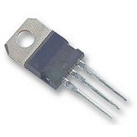
IC, V REG +8.0V, 7808, TO-220-3
Manufacturer
National Semiconductor
Datasheet
1.LM340MP-5.0.pdf
(17 pages)
Specifications of LM7808CT
Output Voltage
8V
Dropout Voltage Vdo
2V
No. Of Pins
3
Voltage Regulator Case Style
TO-220
Operating Temperature Range
0°C To +125°C
Svhc
No SVHC (15-Dec-2010)
Operating Temperature Max
125°C
Output Voltage Fixed
8V
Rohs Compliant
Yes
Lead Free Status / RoHS Status
Lead free / RoHS Compliant
Available stocks
Company
Part Number
Manufacturer
Quantity
Price
Company:

Part Number:
LM7808CT
Manufacturer:
NS
Quantity:
1 250
Part Number:
LM7808CT
Manufacturer:
NS
Quantity:
20 000


www.national.com
V
R
V
Symbol
N
O
IN
LM340 Electrical Characteristics
0˚C ≤ T
Note 1: Absolute Maximum Ratings are limits beyond which damage to the device may occur. Operating Conditions are conditions under which the device functions
but the specifications might not be guaranteed. For guaranteed specifications and test conditions see the Electrical Characteristics.
Note 2: The maximum allowable power dissipation at any ambient temperature is a function of the maximum junction temperature for operation (T
150˚C), the junction-to-ambient thermal resistance (θ
temperature will rise above T
For the TO-3 package (K, KC), the junction-to-ambient thermal resistance (θ
thermal resistance (θ
4˚C/W. If SOT-223 is used, the junction-to-ambient thermal resistance is 174˚C/W and can be reduced by a heatsink (see Applications Hints on heatsinking).
If the TO-263 package is used, the thermal resistance can be reduced by increasing the PC board copper area thermally connected to the package: Using 0.5 square
inches of copper area, θ
Note 3: ESD rating is based on the human body model, 100 pF discharged through 1.5 kΩ.
Note 4: All characteristics are measured with a 0.22 µF capacitor from input to ground and a 0.1 µF capacitor from output to ground. All characteristics except noise
voltage and ripple rejection ratio are measured using pulse techniques (t
must be taken into account separately.
Note 5: Military datasheets are available upon request. At the time of printing, the military datasheet specifications for the LM140K-5.0/883, LM140K-12/883, and
LM140K-15/883 complied with the min and max limits for the respective versions of the LM140. The LM140H and LM140K may also be procured as JAN devices
on slash sheet JM38510/107.
J
≤ +125˚C unless otherwise specified
Output Noise
Voltage
Ripple Rejection
Dropout Voltage
Output Resistance
Short-Circuit Current T
Peak Output
Current
Average TC of V
Input Voltage
Required to
Maintain
Line Regulation
Parameter
JC
Input Voltage (unless otherwise noted)
) of the TO-3 package and the case-to-ambient thermal resistance of the heatsink. For the TO-220 package (T), θ
JA
is 50˚C/W; with 1 square inch of copper area, θ
JMAX
OUT
and the electrical specifications do not apply. If the die temperature rises above 150˚C, the device will go into thermal shutdown.
Output Voltage
V
I
V
T
f = 120 Hz
V
T
f = 1 kHz
T
0˚C ≤ T
T
O
A
J
J
J
J
MIN
MIN
MIN
≤ 500 mA, 0˚C ≤ T
= 25˚C, I
= 25˚C
= 25˚C
= 25˚C, I
= 25˚C, 10 Hz ≤ f ≤ 100 kHz
≤ V
≤ V
≤ V
J
IN
IN
IN
≤ +125˚C, I
JA
≤ V
≤ V
≤ V
Conditions
), and the ambient temperature (T
O
O
= 1A
≤ 1A
MAX
MAX
25˚C
0˚C ≤ T
MAX
I
or I
O
≤ 1A, T
O
O
J
≤ 500 mA,
J
(Note 4) (Continued)
= 5 mA
≤ +125˚C
w
≤ +125˚C
≤ 10 ms, duty cycle ≤ 5%). Output voltage changes due to changes in internal temperature
JA
J
JA
is 37˚C/W; and with 1.6 or more inches of copper area, θ
=
) is 39˚C/W. When using a heatsink, θ
6
Min Typ Max Min Typ Max Min Typ Max
(7.5 ≤ V
7.5
62
62
(7 ≤ V
(8 ≤ V
A
). P
−0.6
10V
DMAX
2.0
2.1
2.4
5V
40
80
IN
IN
8
IN
≤ 25)
≤ 18)
≤ 20)
= (T
1.0
JMAX
14.6
(15 ≤ V
− T
55
55
(14.8 ≤ V
(14.5 ≤ V
A
)/θ
JA
−1.5
12V
19V
27)
30)
JA
2.0
1.5
2.4
75
72
18
is the sum of the 4˚C/W junction-to-case
IN
. If this dissipation is exceeded, the die
≤ 25)
IN
IN
1.0
≤
≤
(17.9 ≤ V
(17.5 ≤ V
17.7
JA
54
54
(18.5 ≤ V
JA
is 32˚C/W.
is 54˚C/W and θ
−1.8
28.5)
15V
23V
2.0
1.2
2.4
90
70
19
JMAX
IN
IN
IN
≤ 30)
≤ 30)
1.0
= 125˚C or
≤
mV/˚C
Units
JC
mΩ
mA
µV
dB
dB
V
V
V
V
A
A
V
is
Related parts for LM7808CT
Image
Part Number
Description
Manufacturer
Datasheet
Request
R

Part Number:
Description:
National Semiconductor [8-Bit D/A Converter]
Manufacturer:
National Semiconductor
Datasheet:
Part Number:
Description:
National Semiconductor [Media Coprocessor]
Manufacturer:
National Semiconductor
Datasheet:
Part Number:
Description:
Digitally Controlled Tone and Volume Circuit with Stereo Audio Power Amplifier, Microphone Preamp Stage and National 3D Sound
Manufacturer:
National Semiconductor
Datasheet:
Part Number:
Description:
Digitally Controlled Tone and Volume Circuit with Stereo Audio Power Amplifier, Microphone Preamp Stage and National 3D Sound
Manufacturer:
National Semiconductor
Datasheet:
Part Number:
Description:
AC97 Rev 2 Codec with Sample Rate Conversion and National 3D Sound
Manufacturer:
National Semiconductor
Part Number:
Description:
Manufacturer:
National Semiconductor
Datasheet:
Part Number:
Description:
Manufacturer:
National Semiconductor
Datasheet:
Part Number:
Description:
General Purpose, Low Voltage, Low Power, Rail-to-Rail Output Operational Amplifiers
Manufacturer:
National Semiconductor
Datasheet:
Part Number:
Description:
8-bit 20 MSPS flash A/D converter.
Manufacturer:
National Semiconductor
Datasheet:
Part Number:
Description:
Low Noise Quad Operational Amplifier
Manufacturer:
National Semiconductor
Datasheet:
Part Number:
Description:
Quad Differential Line Receivers
Manufacturer:
National Semiconductor
Datasheet:
Part Number:
Description:
Quad High Speed Trapezoidal? Bus Transceiver
Manufacturer:
National Semiconductor
Datasheet:
Part Number:
Description:
Dual Line Receiver
Manufacturer:
National Semiconductor
Datasheet:
Part Number:
Description:
TTL to 10k ECL Level Translator with Latch
Manufacturer:
National Semiconductor
Datasheet: