LM3875TF National Semiconductor, LM3875TF Datasheet - Page 13
LM3875TF
Manufacturer Part Number
LM3875TF
Description
Audio Power Amplifier IC
Manufacturer
National Semiconductor
Datasheet
1.LM3875TF.pdf
(20 pages)
Specifications of LM3875TF
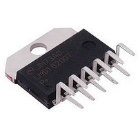
Amplifier Case Style
TO-220
No. Of Pins
11
Peak Reflow Compatible (260 C)
No
Termination Type
Through Hole
Supply Voltage Max
84V
Leaded Process Compatible
No
Mounting Type
Through Hole
Operational Class
Class-AB
Audio Amplifier Output Configuration
1-Channel Mono
Output Power (typ)
56x1@8OhmW
Audio Amplifier Function
Speaker
Input Offset Voltage
10@±35VmV
Input Bias Current
1uA
Total Harmonic Distortion
0.06@8Ohm@40W%
Single Supply Voltage (typ)
24/28V
Dual Supply Voltage (typ)
±12/±15/±18/±24/±28V
Power Supply Requirement
Single/Dual
Power Dissipation
125W
Unity Gain Bandwidth Product (typ)
8MHz
Rail/rail I/o Type
No
Power Supply Rejection Ratio
120dB
Single Supply Voltage (min)
20V
Single Supply Voltage (max)
84V
Dual Supply Voltage (min)
±10V
Dual Supply Voltage (max)
±42V
Operating Temp Range
-20C to 85C
Operating Temperature Classification
Commercial
Mounting
Through Hole
Pin Count
11 +Tab
Package Type
TO-220
Lead Free Status / RoHS Status
Contains lead / RoHS non-compliant
Lead Free Status / RoHS Status
Contains lead / RoHS non-compliant
Available stocks
Company
Part Number
Manufacturer
Quantity
Price

Company:
Part Number:
LM3875TF/NOPB
Manufacturer:
ABB
Quantity:
12


Application Information
THERMAL CONSIDERATIONS
Heat Sinking
The choice of a heat sink for a high-power audio amplifier is
made entirely to keep the die temperature at a level such
that the thermal protection circuitry does not operate under
normal circumstances. The heat sink should be chosen to
dissipate the maximum IC power for a given supply voltage
and rated load.
With high-power pulses of longer duration than 100 ms, the
case temperature will heat up drastically without the use of a
heat sink. Therefore the case temperature, as measured at
the center of the package bottom, is entirely dependent on
heat sink design and the mounting of the IC to the heat sink.
For the design of a heat sink for your audio amplifier appli-
cation refer to the Determining the Correct Heat Sink
section.
Since a semiconductor manufacturer has no control over
which heat sink is used in a particular amplifier design, we
can only inform the system designer of the parameters and
the method needed in the determination of a heat sink. With
this in mind, the system designer must choose his supply
voltages, a rated load, a desired output power level, and
know the ambient temperature surrounding the device.
These parameters are in addition to knowing the maximum
junction temperature and the thermal resistance of the IC,
both of which are provided by National Semiconductor.
As a benefit to the system designer we have provided Maxi-
mum Power Dissipation vs Supply Voltages curves for vari-
ous loads in the Typical Performance Characteristics sec-
tion, giving an accurate figure for the maximum thermal
resistance required for a particular amplifier design. This
data was based on θ
provide a section regarding heat sink determination for any
audio amplifier design where θ
should be noted that the idea behind dissipating the maxi-
mum power within the IC is to provide the device with a low
resistance to convection heat transfer such as a heat sink.
Therefore, it is necessary for the system designer to be
conservative in his heat sink calculations. As a rule, the
lower the thermal resistance of the heat sink the higher the
amount of power that may be dissipated. This is, of course,
guided by the cost and size requirements of the system.
Convection cooling heat sinks are available commercially,
and their manufacturers should be consulted for ratings.
Proper mounting of the IC is required to minimize the thermal
drop between the package and the heat sink. The heat sink
must also have enough metal under the package to conduct
heat from the center of the package bottom to the fins
without excessive temperature drop.
A thermal grease such as Wakefield type 120 or Thermalloy
Thermacote should be used when mounting the package to
the heat sink. Without this compound, the thermal resistance
will be no better than 0.5˚C/W, and probably much worse.
With the compound, thermal resistance will be 0.2˚C/W or
less, assuming under 0.005 inch combined flatness runout
for the package and heat sink. Proper torquing of the mount-
ing bolts is important and can be determined from heat sink
manufacturer’s specification sheets.
Should it be necessary to isolate V
insulating washer is required. Hard washers like berylum
oxide, anodized aluminum and mica require the use of ther-
JC
= 1˚C/W and θ
CS
may be a different value. It
−
from the heat sink, an
CS
= 0.2˚C/W. We also
(Continued)
13
mal compound on both faces. Two-mil mica washers are
most common, giving about 0.4˚C/W interface resistance
with the compound.
Silicone-rubber washers are also available. A 0.5˚C/W ther-
mal resistance is claimed without thermal compound. Expe-
rience has shown that these rubber washers deteriorate and
must be replaced should the IC be dismounted.
Determining Maximum Power Dissipation
Power dissipation within the integrated circuit package is a
very important parameter requiring a thorough understand-
ing if optimum power output is to be obtained. An incorrect
maximum power dissipation (P
inadequate heatsinking, causing thermal shutdown circuitry
to operate and limit the output power.
The following equations can be used to accurately calculate
the maximum and average integrated circuit power dissipa-
tion for your amplifier design, given the supply voltage, rated
load, and output power. These equations can be directly
applied to the Power Dissipation vs Output Power curves in
the Typical Performance Characteristics section.
Equation (1) exemplifies the maximum power dissipation of
the IC and Equations (2), (3) exemplify the average IC power
dissipation expressed in different forms.
where V
where V
where V
Determining the Correct Heat Sink
Once the maximum IC power dissipation is known for a
given supply voltage, rated load, and the desired rated out-
put power the maximum thermal resistance (in ˚C/W) of a
heat sink can be calculated. This calculation is made using
Equation (4) and is based on the fact that thermal heat flow
parameters are analogous to electrical current flow proper-
ties.
It is also known that typically the thermal resistance, θ
(junction to case), of the LM3875 is 1˚C/W and that using
Thermalloy Thermacote thermal compound provides a ther-
mal resistance, θ
explained in the Heat Sinking section.
Referring to the figure below, it is seen that the thermal
resistance from the die (junction) to the outside air (ambient)
is a combination of three thermal resistances, two of which
are known, θ
dissipation) is analogous to current flow, thermal resistance
is analogous to electrical resistance, and temperature drops
are analogous to voltage drops, the power dissipation out of
the LM3875 is equal to the following:
where θ
JA
CC
CC
CC
= θ
P
is the total supply voltage
is the total supply voltage and V
is the total supply voltage.
P
DAVE
JC
DAVE
JC
and θ
P
CS
+ θ
DMAX
= V
P
= (V
(case to heat sink), of about 0.2˚C/W as
CS
DMAX
CS
CC
Opk
= (T
+ θ
. Since convection heat flow (power
V
= V
/R
Opk
SA
Jmax
L
) [V
/π R
CC
D
2
− T
) calculation may result in
CC
/2π
L
− V
Amb
/π − V
2
R
01144910
Opk
)/θ
L
JA
Opk
2
/2 R
Opk
/2]
L
= V
www.national.com
CC
/π
(1)
(2)
(3)
JC
Related parts for LM3875TF
Image
Part Number
Description
Manufacturer
Datasheet
Request
R

Part Number:
Description:
Audio Power Amplifier Series High-Performance 56W Audio Power Amplifier
Manufacturer:
National Semiconductor
Part Number:
Description:
LM387/LM387A Low Noise Dual Preamplifier
Manufacturer:
National Semiconductor
Datasheet:
Part Number:
Description:
LM387 - Low Noise Dual Preamplifier [Discontinued]
Manufacturer:
National Semiconductor
Part Number:
Description:
National Semiconductor [8-Bit D/A Converter]
Manufacturer:
National Semiconductor
Datasheet:
Part Number:
Description:
National Semiconductor [Media Coprocessor]
Manufacturer:
National Semiconductor
Datasheet:
Part Number:
Description:
Digitally Controlled Tone and Volume Circuit with Stereo Audio Power Amplifier, Microphone Preamp Stage and National 3D Sound
Manufacturer:
National Semiconductor
Datasheet:
Part Number:
Description:
Digitally Controlled Tone and Volume Circuit with Stereo Audio Power Amplifier, Microphone Preamp Stage and National 3D Sound
Manufacturer:
National Semiconductor
Datasheet:
Part Number:
Description:
AC97 Rev 2 Codec with Sample Rate Conversion and National 3D Sound
Manufacturer:
National Semiconductor
Part Number:
Description:
Manufacturer:
National Semiconductor
Datasheet:
Part Number:
Description:
Manufacturer:
National Semiconductor
Datasheet:
Part Number:
Description:
General Purpose, Low Voltage, Low Power, Rail-to-Rail Output Operational Amplifiers
Manufacturer:
National Semiconductor
Datasheet:
Part Number:
Description:
8-bit 20 MSPS flash A/D converter.
Manufacturer:
National Semiconductor
Datasheet:
Part Number:
Description:
Low Noise Quad Operational Amplifier
Manufacturer:
National Semiconductor
Datasheet:
Part Number:
Description:
Quad Differential Line Receivers
Manufacturer:
National Semiconductor
Datasheet: