PIC16HV785-E/ML Microchip Technology, PIC16HV785-E/ML Datasheet - Page 87
PIC16HV785-E/ML
Manufacturer Part Number
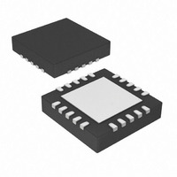
PIC16HV785-E/ML
Description
3.5KB Flash, 128 RAM, 18 I/O 20 QFN 4x4mm TUBE
Manufacturer
Microchip Technology
Series
PIC® 16Fr
Datasheets
1.PIC16F616T-ISL.pdf
(8 pages)
2.PIC16F785-ISS.pdf
(206 pages)
3.PIC16F785-ISS.pdf
(10 pages)
4.PIC16F785-ISS.pdf
(28 pages)
Specifications of PIC16HV785-E/ML
Core Processor
PIC
Core Size
8-Bit
Speed
20MHz
Peripherals
Brown-out Detect/Reset, POR, PWM, WDT
Number Of I /o
17
Program Memory Size
3.5KB (2K x 14)
Program Memory Type
FLASH
Eeprom Size
256 x 8
Ram Size
128 x 8
Voltage - Supply (vcc/vdd)
2 V ~ 5.5 V
Data Converters
A/D 14x10b
Oscillator Type
Internal
Operating Temperature
-40°C ~ 125°C
Package / Case
20-VQFN Exposed Pad, 20-HVQFN, 20-SQFN, 20-DHVQFN
Processor Series
PIC16H
Core
PIC
Data Bus Width
8 bit
Data Ram Size
128 B
Interface Type
RS- 232, USB
Maximum Clock Frequency
32 MHz
Number Of Programmable I/os
18
Number Of Timers
3
Maximum Operating Temperature
+ 125 C
Mounting Style
SMD/SMT
3rd Party Development Tools
52715-96, 52716-328, 52717-734
Development Tools By Supplier
PG164130, DV164035, DV244005, DV164005, PG164120, ICE2000, DV164120, DM163029
Minimum Operating Temperature
- 40 C
On-chip Adc
10 bit, 14 Channel
Lead Free Status / RoHS Status
Lead free / RoHS Compliant
For Use With
AC164324 - MODULE SKT FOR MPLAB 8DFN/16QFN
Connectivity
-
Lead Free Status / Rohs Status
Details
Available stocks
Company
Part Number
Manufacturer
Quantity
Price
Company:

Part Number:
PIC16HV785-E/ML
Manufacturer:
LEGERITY
Quantity:
100


12.1.7
After the A/D module has been configured as desired,
the selected channel must be acquired before the
conversion is started. The analog input channels must
have their corresponding TRIS bits selected as inputs.
To determine sample time, see Table 19-16 and
Table 19-17. After this sample time has elapsed, the
A/D conversion can be started.
These steps should be followed for an A/D conversion:
1.
2.
3.
4.
5.
6.
7.
© 2008 Microchip Technology Inc.
Configure the A/D module:
• Configure analog/digital I/O (ANSx)
• Select A/D conversion clock in the ADCON1
• Configure voltage reference in the ADCON0
• Select A/D input channel in the ADCON0
• Select result format in the ADCON0 Register
• Turn on A/D module in the ADCON0 Register
Configure A/D interrupt (if desired):
• Clear ADIF bit of the PIR1 Register
• Set ADIE bit of the PIE1 Register
• Set PEIE and GIE bits of the INTCON Regis-
Wait the required acquisition time.
Start conversion:
• Set GO/DONE bit (ADCON0<1>)
Wait for A/D conversion to complete, by either:
• Polling for the GO/DONE bit to be cleared
• Waiting for the A/D interrupt
Read A/D Result register pair
(ADRESH:ADRESL), clear bit ADIF if required.
For next conversion, go to step 1 or step 2 as
required. The A/D conversion time per bit is
defined as T
required before the next acquisition starts.
Register
Register
Register
ter
(with interrupts disabled); OR
CONFIGURING THE A/D
AD
. A minimum wait of 2 T
AD
is
EXAMPLE 12-1:
;This code block configures the A/D
;for polling, Vdd reference, R/C clock
;and RA0 input.
;
;Conversion start and wait for complete
;polling code included.
;
BCF
BSF
MOVLW
MOVWF
BSF
BSF
BCF
MOVLW
MOVWF
CALL
BSF
BTFSC
GOTO
MOVF
MOVWF
BSF
MOVF
BCF
MOVWF
PIC16F785/HV785
STATUS,RP1
STATUS,RP0
B’01110000’ ;A/D RC clock
ADCON1
TRISA,0
ANSEL0,0
STATUS,RP0
B’10000001’ ;Right, Vdd Vref, AN0
ADCON0
SampleTime
ADCON0,GO
ADCON0,GO
$-1
ADRESH,W
RESULTHI
STATUS,RP0
ADRESL,W
STATUS,RP0
RESULTLO
A/D CONVERSION
;Bank 1
;
;Set RA0 to input
;Set RA0 to analog
;Bank 0
;Wait min sample time
;Start conversion
;Is conversion done?
;No, test again
;Read upper 2 bits
;Bank 1
;Read lower 8 bits
;Bank 0
DS41249E-page 85
Related parts for PIC16HV785-E/ML
Image
Part Number
Description
Manufacturer
Datasheet
Request
R

Part Number:
Description:
Manufacturer:
Microchip Technology Inc.
Datasheet:
Part Number:
Description:
Manufacturer:
Microchip Technology Inc.
Datasheet:
Part Number:
Description:
Manufacturer:
Microchip Technology Inc.
Datasheet:
Part Number:
Description:
Manufacturer:
Microchip Technology Inc.
Datasheet:
Part Number:
Description:
Manufacturer:
Microchip Technology Inc.
Datasheet:
Part Number:
Description:
Manufacturer:
Microchip Technology Inc.
Datasheet:
Part Number:
Description:
Manufacturer:
Microchip Technology Inc.
Datasheet:
Part Number:
Description:
Manufacturer:
Microchip Technology Inc.
Datasheet: