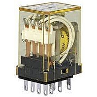
RY22S-UDC24V IDEC, RY22S-UDC24V Datasheet

RY22S-UDC24V
Specifications of RY22S-UDC24V
Related parts for RY22S-UDC24V
RY22S-UDC24V Summary of contents
Page 1
... RY4S-UL RY4V-UL RY4S-UC RY4S-ULC RY4S-UT RY4S-UD — RY4S-ULD RY22S-U RY22V-U RY22S-UL RY22V-UL RY22S-UT RY22S-UD RY22V-UD RY42S-U RY42V-U RY42S-UL RY42V-UL RY42S-UT Ordering Information When ordering, specify the Part No. and coil voltage code: USA: 800-262-IDEC Canada: 888-317-IDEC RY/RM Series Coil Voltage Code AC6V, AC12V, AC24V, AC110V, AC120V, ...
Page 2
... RY2S RY22S Pullover Wire RM2 Spring RY4S RY42S RY2S, RY22S Leaf Spring* (side latch) RM2, RY4S, RY42S RY2S, RY22S Leaf Spring* RM2 (top latch) RY4S, RY42S *Not available for PCB mount socket SY4S-62. Accessories Description Appearance Aluminum DIN Rail (1 meter length) ...
Page 3
... Relays with indicator or diode: 1000V AC, 1 minute 4. For use under different temperature conditions, refer to Continuous Load Current vs. Operating Temperature Curve. The operating temperature range of relays with indicator or diode is –25 to +40°C. USA: 800-262-IDEC Canada: 888-317-IDEC RY/RM Series Bifurcated Contact RY4 - 4PDT RY22 - DPDT / RY42 - 4PDT Silver-palladium alloy 100 mΩ ...
Page 4
... UL Ratings (Bifurcated Contact) Voltage Resistive General use 240V AC 0.8A 0.4A 120V AC 1A 0.5A 30V DC 1A 0.5A www.idec.com Relays & Sockets Operation Characteristics (against rated values at 20ºC) Max. Continuous Pickup Dropout Applied Voltage Voltage Voltage 30% 110% 80% maximum minimum Operation Characteristics (against rated values at 20º ...
Page 5
... USA: 800-262-IDEC Canada: 888-317-IDEC RY/RM Series Wire Size Torque Maximum up to 2–#14AWG 5 in•lbs Maximum up to 2–#14AWG 5 in•lbs Maximum up to 2–#14AWG 5 in•lbs Maximum up to 2–#14AWG 5 in• ...
Page 6
... DC inductive 100 50 20 100V DC resistive 100V DC inductive 10 1 Load Current (A) 768 Characteristics (Reference Data) (RY4) 1000 3 (RM2) 1000 (RY4) 1000 3 (RM2) www.idec.com Relays & Sockets 500 240V AC resistive 200 100 240V AC inductive Load Current (A) 110V AC resistive 220V AC resistive 500 100 ...
Page 7
... DC Coil Coil Load Current (A) USA: 800-262-IDEC Canada: 888-317-IDEC RY/RM Series AC resistive AC inductive DC resistive DC inductive 100 200 300 Load Voltage (V) AC resistive AC inductive DC DC inductive resistive 100 200 300 Load Voltage (V) (RM2) 100 90 ...
Page 8
... DPDT Wide (RM2 Coil 24V and (+)14 over 13(–) www.idec.com Relays & Sockets With Check Button Front 3 4 Pushbutton Contacts can be operated by pressing the ( + ) 14 check button. 4PDT (RY4/RY42 When the relay is energized, 13(–) (+)14 the indicator goes on. The LED protection diode • ...
Page 9
... RY2V/RY22V 0.5 8-ø1 holes 35.6 max 4.4 RY2S-UT/RY22S-UT 3 × ø1.2 oblong hole 3.5 2 14.5 35.6 max. 5.4 Dimensions (mm) RY4S/RY42S Total length from the panel surface including relay socket SY4S-05: 61.5 ( 63.5 ) max., SY4S-51: 39.6 ( 41.6 ) max. 2.2 × ø1.2 oblong hole Dimensions in the ( ) include a hold-down spring ...
Page 10
... Top View ) 26 Terminal Arrangement 2-ø4.2 Mounting Holes (or M4 Tapped Holes Top View ) www.idec.com Relays & Sockets 31.5 18 DIN Rail M3 Terminal (BNDN) Terminal Arrangement Screw 2-ø4.2 Mounting Holes (or M4 Tapped Holes max. 4.8 min. 18.5 5.9 max. 25 ø3.2 min. DIN Rail 35.5 ...
Page 11
... N: No. of sock ∗ 10.4 min. when using hold-do SY4S-61 13.6 min. 4.4 27 8-ø2 holes ±0.1) (Tolerance 1.5 21 USA: 800-262-IDEC Canada: 888-317-IDEC RY/RM Series Panel Thickness: [27 (N–1) + 21. Terminal Arrangement No. of sockets mo (Bottom View) 11 18.7 ∗ 10.4 min. when using hold-down sp 13 ...
Page 12
... Soldering 1. When soldering the relay terminals, use a soldering iron 60W, and quickly complete soldering (within approximately 3 seconds). 2. Use a non-corrosive rosin fl ux. www.idec.com Relays & Sockets This protection circuit can be used when the load impedance is smaller than the RC impedance load power circuit. ...
Page 13
... Add another surge absorbing provision to the relay to prevent damage. Operating Instructions con’ and CSA ratings may differ from product rated values determined by IDEC not use relays in the vicinity of strong magnetic fi eld, as this may affect relay operation. ...


