S4-12VDC PANASONIC EW, S4-12VDC Datasheet
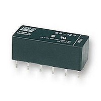
RELAY, PCB, 4PNO, 12VDC

S4-12VDC

Manufacturer Part Number
S4-12VDC
Description
RELAY, PCB, 4PNO, 12VDC
Manufacturer
PANASONIC EW
Datasheet

Specifications of S4-12VDC

Relay Type
Power
Coil Voltage Vdc Nom
12V
Contact Current Max
4A
Contact Voltage Ac Nom
250V
Contact Voltage Dc Nom
30V
Coil Resistance
720ohm
Coil Type
DC Coil, Monostable
Coil Current
16.7mA
Nom
RoHS Compliant
Contact Configuration
4PNO
Rohs Compliant
Yes
SPECIFICATIONS
Contacts
Coil (polarized) (at 20°C 68°F)
Notes:
**
Remarks
* Specifications will vary with foreign standards certification ratings.
*
*
*
*
*
*
*
TYPICAL APPLICATIONS
Telecommunications equipment, data processing equipment,
facsimiles, alarm equipment, measuring equipment.
en_ds_61105_0000: 130804D
Arrangement
Initial contact resistance, max.
(By voltage drop 6 V DC 1 A)
Initial contact pressure
Contact material
Electrostatic capacitance
Thermal electromotive force
(at nominal coil voltage)
Rating
(resistive)
Expected
life (min.
operations)
Single side
stable
Latching
1
2
3
4
5
6
7
1
Measurement at same location as “Initial breakdown voltage” section
Detection current: 10mA
Excluding contact bounce time
Half-wave pulse of sine wave: 11ms; detection time: 10µs
Half-wave pulse of sine wave: 6ms
Detection time: 10µs
Refer to 6. Conditions for operation, transport and storage mentioned in
AMBIENT ENVIRONMENT (see catalog).
This value can change due to the switching frequency, environmental
conditions, and desired reliability level, therefore it is recommended to check this
with the actual load.
1.102
Nominal switching capacity
Maximum switching power
Maximum switching voltage
Max. switching current
Min. switching capacity**
Mechanical (at 50 cps)
Electrical
(at 20 cpm)
Minimum operating power
Nominal operating power
Minimum set and reset
Nominal set and reset
28.0
4 A 250 V AC
3 A 30 V DC
12.0
.472
10.4
.409
mm
1
THE VARIETY OF CONTACT
inch
4 A 250 V AC, 3 A 30 V DC
(48 VDC at less than 0.5 A)
Gold clad silver alloy
2 Form A 2 Form B,
3 Form A 1 Form B,
Approx. 12 g
250 V AC, 30 V DC
100µA 100 m V DC
4 A (AC), 3 A (DC)
Approx. 100 mW
Approx. 200 mW
Approx. 100 mW
Approx. 200 mW
1,000 VA, 90 W
ARRANGEMENTS
FEATURES
• The variety of contact arrangements
2 Form A 2 Form B, 3 Form A 1 Form
B, 4 Form A
• Latching types available
• High sensitivity in small size 100 mW
pick-up and 200 mW nominal
operating power
• High shock and vibration resistance
Shock: 50 G Vibration: 10 to 55 Hz at
double amplitude of 3 mm
Approx. 3µV
Approx. 3pF
4 Form A
4 A CAPACITY,
50 mΩ
2 × 10
10
10
8
5
5
.42 oz
Characteristics (at 25°C
Max. operating speed
Initial insulation resistance*
Initial
breakdown
voltage*
Operate time*
(at nominal voltage)(at 20°C)
Release time (without diode)*
(at nominal voltage)(at 20°C)
Set time*
(at nominal voltage)(at 20°C)
Reset time*
(at nominal voltage)(at 20°C)
Initial contact bounce, max.
Temperature rise
(at nominal voltage)(at 20°C)
Shock resistance
Vibration resistance
Conditions for operation,
transport and storage*
(Not freezing and condens-
ing at low temperature)
Unit weight
.118 inch
2
3
(latching)
3
(latching)
Between open contacts
Between contact sets
Between contacts and
coil
3
7
Functional*
Destructive*
Functional*
Destructive
S RELAYS
• Wide switching range From 100µA
100 mV DC to 4 A 250 V AC
• Low thermal electromotive force
Approx. 3 µV
• Dual-In-Line packaging arrangement
1
77°F
Ambient
temp.
Humidity
3
50% Relative humidity)
4
6
5
176.4 m/s
235.2 m/s
at double amplitude of 3 mm
at double amplitude of 4 mm
Max. 35°C with nominal coil
Max. 15 ms (Approx. 8 ms)
Max. 10 ms (Approx. 5 ms)
Max. 15 ms (Approx. 8 ms)
20 cpm for maximum load,
voltage and at maximum
50 cps for low-level load
10,000 MΩ at 500 V DC
Min. 980 m/s
Min. 490 m/s
Approx. 8 g
switching current
–40°F to +149°F
–40°C to +65°C
(1 mA 1 V DC)
5 to 85% R.H.
1,000 Vrms
1,500 Vrms
2
2
750 Vrms
{18 G}, 10 to 55 Hz
{24 G}, 10 to 55 Hz
1 ms
2
2
.28 oz
{100 G}
{50 G}
S
1

Related parts for S4-12VDC

S4-12VDC Summary of contents

Page 1

... Electrical operations) (at 20 cpm Coil (polarized) (at 20°C 68°F) Minimum operating power Single side stable Nominal operating power Minimum set and reset Latching Nominal set and reset Notes: ** This value can change due to the switching frequency, environmental 1 conditions, and desired reliability level, therefore it is recommended to check this with the actual load ...

Page 2

... Nominal Inductance, operating ± ( 10%) mH power, Coil II Coil I Coil 200 130 31 31 192 180 40 40 200 720 170 170 200 2,850 680 680 202 6,500 1,250 1,250 355 PC board pattern (Copper-side view) 12-1 ...

Page 3

... Diagram shows the “reset” position when terminals 6 Set and 7 are energized. Energize terminals 1 and 12 to transfer contacts. REFERENCE DATA 1. Maximum switching power 1,000 DC resistive load AC resistive load 100 10 0 Contact current, A 4.-(1) Coil temperature rise Tested Sample: S4-24V, 4 Form A 100 0.2 0.4 0.6 0.8 1 ...

Page 4

... G Specifications Breakdown voltage Insulation resistance Heat resistance Maximum continuous current (Note: Don't insert or remove relays while in the energized condition.) 0.4±0.1 .016±.004 3.4±0.3 .134±.012 7.62±0.3 .300±.012 Terminal width: 1.3 .051 Terminal thickness: 1 ...

Page 5

... By shorting terminals 12 and 7, apply plus to 1, minus set and plus to 6, minus reset. Applied coil voltage should be the same as the nominal. Operating power will be reduced to one- half. CAUTIONS FOR USE Based on regulations regarding insulation distance, there is a restriction on same-channel load connections between terminals No ...

Related keywords