G6JU-2FSY 5DC Omron, G6JU-2FSY 5DC Datasheet - Page 10
G6JU-2FSY 5DC
Manufacturer Part Number
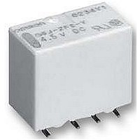
G6JU-2FSY 5DC
Description
RELAY, SMD, DPDT, 5VDC, LATCHING
Manufacturer
Omron
Datasheet
1.G6J-2FSY_12DC.pdf
(10 pages)
Specifications of G6JU-2FSY 5DC
Contact Current Max
1A
Contact Voltage Ac Nom
125V
Contact Voltage Dc Nom
30V
Coil Voltage Vdc Nom
5V
Coil Resistance
245.5ohm
Coil Power Cont
100mW
Coil Type
DC Coil
Coil Current
20.4mA
Contact Configuration
DPDT
Rohs Compliant
Yes
Lead Free Status / RoHS Status
Lead free / RoHS Compliant


G6J-Y
Precautions
Refer to page 25 for information on general precautions. Be sure to read these precautions before using the Relay.
Correct Use
• Long Term Current Carrying
Handling of Surface-mounting Relays
Use the Relay as soon as possible after opening the moisture-
proof package. If the Relay is left for a long time after opening the
moisture-proof package, the appearance may suffer and seal
failure may occur after the solder mounting process. To store the
Relay after opening the moisture-proof package, place it into the
original package and sealed the package with adhesive tape.
When washing the product after soldering the Relay to a PCB,
use a water-based solvent or alcohol-based solvent, and keep the
solvent temperature to less than 40 ° C. Do not put the relay in a
cold cleaning bath immediately after soldering.
Soldering
Soldering temperature: Approx. 250°C (At 260°C if the DWS
method is used.)
Soldering time: Approx. 5 s max. (Approx. 2 s for the first time and
approx. 3 s for the second time if the DWS method is used.)
Be sure to adjust the level of the molten solder so that the solder
will not overflow onto the PCB.
Claw Securing Force During Automatic Insertion
During automatic insertion of Relays, make sure to set the
securing force of the claws to the following values so that the
Relay characteristics will be maintained.
Environmental Conditions During Operation, Storage, and
Transportation
Protect the Relays from direct sunlight and keep the Relays under
normal temperature, humidity, and pressure.
90
Cat. No. K125-E1-02
Do not attach them to the center area or to only part of the Relay.
Under a long-term current carrying without switching, the
insulation resistance of the coil goes down gradually due to the
heat generated by the coil itself. Furthermore, the contact
resistance of the Relay will gradually become unstable due to the
generation of film on the contact surfaces. A Latching Relay can
be used to prevent these problems. When using a single-side
stable relay, the design of the fail-safe circuit provides protection
against contact failure and open coils.
Secure the claws to the area indicated by shading.
Direction A: 4.90 N max.
Direction B: 9.80 N max.
Direction C: 9.80 N max.
ALL DIMENSIONS SHOWN ARE IN MILLIMETERS.
To convert millimeters into inches, multiply by 0.03937. To convert grams into ounces, multiply by 0.03527.
A
C
B
Mounting Latching Relays
Make sure that the vibration or shock that is generated from other
devices, such as Relays in operation, on the same panel and
imposed on the Latching Relays does not exceed the rated value,
otherwise the Latching Relays that have been set may be reset or
vice versa. The Latching Relays are reset before shipping. If
excessive vibration or shock is imposed, however, the Latching
Relays may be set accidentally. Be sure to apply a reset signal
before use.
Maximum Voltage
The maximum voltage of the coil can be obtained from the coil
temperature increase and the heat-resisting temperature of coil
insulating sheath material. (Exceeding the heat-resisting
temperature may result in burning or short-circuiting.) The
maximum voltage also involves important restrictions which
include the following:
• Must not cause thermal changes or deterioration of the insulating
• Must not cause damage to other control devices.
• Must not cause any harmful effect on people.
• Must not cause fire.
Therefore, be sure not to exceed the maximum voltage specified
in the catalog.
As a rule, the rated voltage must be applied to the coil. A voltage
exceeding the rated value, however, can be applied to the coil
provided that the voltage is less than the maximum voltage. It
must be noted that continuous voltage application to the coil will
cause a coil temperature increase thus affecting characteristics
such as electrical life and resulting in the deterioration of coil
insulation.
Coating
Relays mounted on PCBs may be coated or washed. Do not
apply silicone coating or detergent containing silicone, otherwise
the silicone coating or detergent may remain on the surface of the
Relays.
Other Handling
Please don’t use the relay if it suffered the dropping shock.
Because there is a possibility of something damage for initial
performance.
material.
G6J-Y
Related parts for G6JU-2FSY 5DC
Image
Part Number
Description
Manufacturer
Datasheet
Request
R

Part Number:
Description:
RELAY LATCH DPDT 1A 12VDC SMD
Manufacturer:
Omron
Datasheet:

Part Number:
Description:
Low Signal SMT Latching Relay
Manufacturer:
Omron
Datasheet:

Part Number:
Description:
SMT Tape & Reel Latching Relay
Manufacturer:
Omron
Datasheet:
Part Number:
Description:
SMT Tape & Reel Latching Relay
Manufacturer:
Omron
Datasheet:
Part Number:
Description:
Low Signal Relays - PCB DPDT 1-Coil 3 VDC 1A 100mW Latch Short
Manufacturer:
Omron
Datasheet:
Part Number:
Description:
RELAY DPDT 24VDC LATCH SMT
Manufacturer:
Omron
Datasheet:
Part Number:
Description:
RELAY DPDT 5VDC LATCH SMT
Manufacturer:
Omron
Datasheet:
Part Number:
Description:
RELAY DPDT 12VDC LATCH SMT
Manufacturer:
Omron
Datasheet:
Part Number:
Description:
SIGNAL RELAY, DPDT, 12VDC, 1A, SMD
Manufacturer:
Omron
Datasheet:
Part Number:
Description:
SIGNAL RELAY, DPDT, 24VDC, 1A, SMD
Manufacturer:
Omron
Datasheet:
Part Number:
Description:
SIGNAL RELAY, DPDT, 4.5VDC, 1A, SMD
Manufacturer:
Omron
Datasheet:
Part Number:
Description:
SMT Low Signal Relay
Manufacturer:
Omron
Datasheet:
Part Number:
Description:
Low Signal Latching Relay, 1A, DPDT, 140mW, SMT 4.8mm Terminal Width, 4.5VDC
Manufacturer:
Omron
Datasheet: