80.41.0.240.0000 FINDER, 80.41.0.240.0000 Datasheet - Page 2
80.41.0.240.0000
Manufacturer Part Number
80.41.0.240.0000
Description
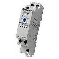
Time Delay Relay
Manufacturer
FINDER
Datasheet
1.80.11.0.240.0000.pdf
(8 pages)
Specifications of 80.41.0.240.0000
Contact Configuration
SPDT
Nom Input Voltage
240V
Timing Adjustment
Screwdriver Slot
Relay Mounting
DIN Rail
Length/height, External
88.8mm
External Width
17.5mm
External Depth
60.8mm
Lead Free Status / RoHS Status
Lead free / RoHS Compliant


80.21
17.5
Features
Mono-function timer range
80.21 - ON pulse, multi-voltage
80.41 - Signal OFF delay, multi-voltage
80.91 - Asymmetrical recycling, multi-voltage
•
•
•
•
•
•
80.21 / 80.41 / 80.91
Screw terminal
F
S
2
Contact specification
Contact configuration
Rated current/Maximum peak current
Rated voltage/Maximum switching voltage V AC
Rated load AC1
Rated load AC15 (230 V AC)
Single phase motor rating (230 V AC)
Breaking capacity DC1: 30/110/220 V
Minimum switching load
Standard contact material
Supply specification
Nominal voltage (U
Rated power AC/DC
Operating range
Technical data
Specified time range
Repeatability
Recovery time
Minimum control impulse
Setting accuracy-full range
Electrical life at rated load in AC1
Ambient temperature range
Protection category
Approvals (according to type)
OR
17.5 mm wide
Six time scales from 0.1s to 20h
High input/output isolation
35 mm rail (EN 50022) mount
"Blade + cross" - both flat blade and cross head
screw drivers can be used to adjust the range
and function selectors, the timing trimmer, and
to disengage the rail mounting clip
New multi-voltage versions with "PWM clever"
technology
EE
“General technical information” page V
UL H
80.41
17.5
ORSEPOWER AND
80.91
17.5
N
)
P
ILOT
D
V AC (50/60 Hz)
UTY RATINGS
60.8
VA (50 Hz)/W
mW (V/mA)
cycles
V DC
kW
AC
DC
VA
VA
ms
ms
°C
%
%
A
A
•
•
DI: ON pulse
Multi-voltage
Mono-function
(without signal START)
Wiring diagram
16/0.3/0.12
1 CO (SPDT)
500 (10/5)
< 1.8 / < 1
(17...265)V
(17...265)V
–10…+50
N/-
250/400
A2
24...240
24...240
18 15 16
100·10
AgCdO
16/30
80.21
4000
0.55
IP 20
≤ 50
750
± 1
± 5
A1
(0.1…2)s, (1…20)s, (0.1…2)min, (1…20)min, (0.1…2)h, (1…20)h
—
L/+
3
•
•
BE: Signal OFF delay
Multi-voltage
Mono-function
80 Series - Modular timers 16 A
(with signal START)
Wiring diagram
16/0.3/0.12
1 CO (SPDT)
(17...265)V
(17...265)V
500 (10/5)
< 1.8 / < 1
–10…+50
N/-
250/400
A2
24...240
24...240
18 15
100·10
AgCdO
80.41
16/30
4000
IP 20
0.55
≤ 50
750
± 1
± 5
50
A1
L/+
16
B1
3
S
Wiring diagram
•
•
LI: Asymmetrical recycling
LE: Signal asymmetrical recycling
(without signal
Multi-voltage
Mono-function
N/-
A2
18 15
(ON starting)
(ON starting)
START)
A1
L/+
16/0.3/0.12
(10.2...265)V
(10.2...265)V
1 CO (SPDT)
16
B1
500 (10/5)
< 1.8 / < 1
–10…+50
250/400
12...240
12...240
100·10
AgCdO
80.91
16/30
4000
IP 20
≤ 50
750
0.55
± 1
± 5
50
Wiring diagram
N/-
(with signal
A2
18 15
3
START)
A1
L/+
16
B1
S
Related parts for 80.41.0.240.0000
Image
Part Number
Description
Manufacturer
Datasheet
Request
R

Part Number:
Description:
JUMPER LINK, 20WAY
Manufacturer:
FINDER
Datasheet:


Part Number:
Description:
INTERFACE RELAY, SPDT-CO, 24VAC/DC
Manufacturer:
FINDER
Datasheet:
Part Number:
Description:
INTERFACE RELAY, SPDT-CO, 24VDC
Manufacturer:
FINDER
Datasheet:

Part Number:
Description:
RELAY, SCREW TERM, 6A, 12VAC/DC
Manufacturer:
FINDER
Datasheet:
Part Number:
Description:
RELAY, SCREW TERM, 6A, 48VAC/DC
Manufacturer:
FINDER
Datasheet:
Part Number:
Description:
RELAY, SCREW TERM, 6A, 125VAC/DC
Manufacturer:
FINDER
Datasheet:
Part Number:
Description:
RELAY, SCREW TERM, 6A, 240VAC/DC
Manufacturer:
FINDER
Datasheet:
Part Number:
Description:
RELAY, SCREW TERM, 6A, 6VDC
Manufacturer:
FINDER
Datasheet:
Part Number:
Description:
RELAY, SCREW TERM, 6A, 12VDC
Manufacturer:
FINDER
Datasheet:
Part Number:
Description:
RELAY, SCRW TER, DPDT, 8A, 24VAC/DC
Manufacturer:
FINDER
Datasheet:
Part Number:
Description:
RELAY, SCREW TERM, DPDT, 8A, 12VDC
Manufacturer:
FINDER
Datasheet:
Part Number:
Description:
RELAY, SCREW TERM, DPDT, 8A, 24VDC
Manufacturer:
FINDER
Datasheet:

Part Number:
Description:
RELAY, SCREWLESS, 6A, 24VDC
Manufacturer:
FINDER
Datasheet: