80.41.0.240.0000 FINDER, 80.41.0.240.0000 Datasheet - Page 6
80.41.0.240.0000
Manufacturer Part Number
80.41.0.240.0000
Description
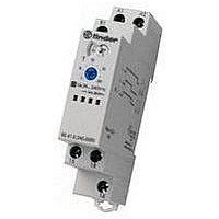
Time Delay Relay
Manufacturer
FINDER
Datasheet
1.80.11.0.240.0000.pdf
(8 pages)
Specifications of 80.41.0.240.0000
Contact Configuration
SPDT
Nom Input Voltage
240V
Timing Adjustment
Screwdriver Slot
Relay Mounting
DIN Rail
Length/height, External
88.8mm
External Width
17.5mm
External Depth
60.8mm
Lead Free Status / RoHS Status
Lead free / RoHS Compliant


Functions
Wiring diagram
Without signal START
With signal START
L
N
6
N/-
N/-
N/-
N/-
A2
A2
18 15
A2
18 15
18 15 16
A2
18 15
K2
A1
A2
U = Supply voltage
S = Signal switch
A1
A1
A1
A1
N/–
L/+
L/+
A2
N/–
L/+
L/+
A2
= Output contact
B1
16
B1
B1
S
S
B1
L/+
A1
L/+
A1
K1
80.01
80.01
B1
B1
80.71
80.71
*
**
S
S
NOTE: The function must be set before energising the timer.
• Possible to control an external load, such as another relay coil or timer, connected to the signal start terminal B1.
* With DC supply, positive polarity has to be connected to B1 terminal (according to EN 60204-1).
** A voltage other than the supply voltage can be applied to the command Start (B1), example:
* The LED on type 80.61 is illuminated only when the supply voltage is applied to the timer; during the timing period
80.01
80.71
80.01
80.71
Type
the LED is not illuminated.
A1 - A2 = 230 V AC
B1 - A2 = 12 V DC
Without signal Start = Start via contact in supply line (A1).
With signal Start = Start via contact into control terminal (B1).
U
U
U
U
S
U
S
U
S
LED*
T
T
T
T
T
T
T
T
T
T
T
T
T
t<T
T
80 Series - Modular timers 1 - 6 - 8 - 16 A
Supply voltage
T
T
T
OFF
ON
ON
ON
t<T
t<T
T
t<T
t<T
(AI)
Apply power to timer. Output contacts transfer after preset
time has elapsed. Reset occurs when power is removed.
(DI)
Apply power to timer. Output contacts transfer immediately.
After the preset time has elapsed, contacts reset.
(SW)
Apply power to timer. Output contacts transfer immediately
and cycle between ON and OFF for as long as power is
applied. The ratio is 1:1 (time on = time off).
(BE)
Power is permenently applied to the timer. The output
contacts transfer immediately on closure of the Signal
Switch (S). Opening the Signal Switch initiates the preset
delay, after which time the output contacts reset.
(CE)
Power is permenently applied to the timer. Closing the
Signal Switch (S) initiates the preset delay, after which time
the output contacts transfer. Opening the Signal switch
initiates the same preset delay, after which time the output
contacts reset.
(DE)
Power is permenently applied to the timer.
On momentary or maintained closure of Signal Switch (S),
the output contacts transfer, and remain so for the duration
of the preset delay, after which they reset.
(Timing in Progress)
NO output contact
ON delay.
ON pulse.
Signal OFF delay.
Signal ON and OFF delay.
Signal ON pulse.
Symmetrical recycling: ON start.
Closed
Open
Open
Open
15 - 18
15 - 18
15 - 18
15 - 16
Open
Contacts
15 - 16
15 - 16
15 - 16
15 - 18
Closed
Related parts for 80.41.0.240.0000
Image
Part Number
Description
Manufacturer
Datasheet
Request
R

Part Number:
Description:
JUMPER LINK, 20WAY
Manufacturer:
FINDER
Datasheet:


Part Number:
Description:
INTERFACE RELAY, SPDT-CO, 24VAC/DC
Manufacturer:
FINDER
Datasheet:
Part Number:
Description:
INTERFACE RELAY, SPDT-CO, 24VDC
Manufacturer:
FINDER
Datasheet:

Part Number:
Description:
RELAY, SCREW TERM, 6A, 12VAC/DC
Manufacturer:
FINDER
Datasheet:
Part Number:
Description:
RELAY, SCREW TERM, 6A, 48VAC/DC
Manufacturer:
FINDER
Datasheet:
Part Number:
Description:
RELAY, SCREW TERM, 6A, 125VAC/DC
Manufacturer:
FINDER
Datasheet:
Part Number:
Description:
RELAY, SCREW TERM, 6A, 240VAC/DC
Manufacturer:
FINDER
Datasheet:
Part Number:
Description:
RELAY, SCREW TERM, 6A, 6VDC
Manufacturer:
FINDER
Datasheet:
Part Number:
Description:
RELAY, SCREW TERM, 6A, 12VDC
Manufacturer:
FINDER
Datasheet:
Part Number:
Description:
RELAY, SCRW TER, DPDT, 8A, 24VAC/DC
Manufacturer:
FINDER
Datasheet:
Part Number:
Description:
RELAY, SCREW TERM, DPDT, 8A, 12VDC
Manufacturer:
FINDER
Datasheet:
Part Number:
Description:
RELAY, SCREW TERM, DPDT, 8A, 24VDC
Manufacturer:
FINDER
Datasheet:

Part Number:
Description:
RELAY, SCREWLESS, 6A, 24VDC
Manufacturer:
FINDER
Datasheet: