TR-51666-16 MACROMATIC CONTROLS, TR-51666-16 Datasheet - Page 3
TR-51666-16
Manufacturer Part Number
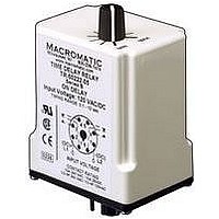
TR-51666-16
Description
TIME DELAY RELAY, SPDT, 60MIN, 12VAC/DC
Manufacturer
MACROMATIC CONTROLS
Datasheet
1.TR-51662-05.pdf
(30 pages)
Specifications of TR-51666-16
Contact Configuration
SPDT
Nom Input Voltage
12V
Delay Time Range
0.6min To 60min
Timing Adjustment
Knob
Relay Mounting
Plug In
Lead Free Status / RoHS Status
Lead free / RoHS Compliant


TIME DELAY RELAYS
Definition of Timing Functions
Understanding the differences between all the functions available in time delay relays can sometimes be a daunting task. To
begin with, time delay relays are simply control relays with a time delay built in. Their purpose is to control an event based on
time.
Typically, time delay relays are initiated or triggered by one of two methods:
These trigger signals can be one of two designs: a control switch (dry contact), i.e., limit switch, push button, float switch, etc., or
by voltage (commonly known as a power trigger).
To help understand, some definitions are important:
Below and on the following page are both written and visual descriptions on how the common timing functions operate. A Timing
Chart shows the relationship between Input Voltage, Trigger Signal (if present) and Output Contacts. If you cannot find a product
to fit your requirements or have any questions, Macromatic�s Application Engineers offer technical information along with product
selection and application assistance. Just call us at 800-238-7474 or e-mail us at tech-help@macromatic.com.
52
Function
ON DELAY
Delay on Operate
Delay on Make
INTERVAL ON
Interval
OFF DELAY
Delay on Release
Delay on
Delay on Drop-Out
SINGLE SHOT
One Shot
Momentary
u application of input voltage (On Delay, Interval On, Flasher, Repeat Cycle & Delayed Interval)
u opening or closing of a trigger signal (Off Delay, Single Shot, Watchdog & Triggered Delayed Interval)
u Input Voltage - control voltage applied to the input terminals. Depending on the function, input voltage will either initiate
u Trigger Signal - on certain timing functions, a trigger signal is used to initiate the unit after input voltage has been applied.
u Output (Load) - every time delay relay has an internal relay (usually mechanical) with contacts that open & close to
De-Energization
Interval
the unit or make it ready to initiate when a trigger signal is applied.
As noted above, this trigger signal can either be a control switch (dry contact switch) or a power trigger (voltage).
control the load. They are represented by the dotted lines in the wiring diagrams. Note that the user must provide the
voltage to power the load being switched by the output contacts of the time delay relay.
Operation
Upon application of input voltage, the preset time
begins. At the end of the preset time, the relay is
energized. Input voltage must be removed and
reapplied to reset the time delay & de-energize
the relay.
Upon application of input voltage, the relay is
energized and the preset time begins. At the end
of the preset time, the relay is de-energized.
Input voltage must be removed and reapplied to
reset the time delay.
Upon application of input voltage, the time delay
relay is ready to accept trigger signals. Upon
application of the trigger signal, the relay is
energized. Upon release of the trigger signal, the
preset time begins. At the end of the preset time,
the relay is de-energized. Any application of the
trigger signal during the preset time will keep the
relay energized & reset the time delay.
Upon application of input voltage, the time delay
relay is ready to accept trigger signals. Upon
application of the trigger signal, the relay is
energized and the preset time begins. During the
preset time, the trigger signal is ignored. The
time delay relay is reset by applying the trigger
signal when the relay is not energized.
Timing Chart
1/09
Related parts for TR-51666-16
Image
Part Number
Description
Manufacturer
Datasheet
Request
R


Part Number:
Description:
FUSE 5.00A 32V FAST 1206 SMT
Manufacturer:
Cooper/Bussmann
Datasheet:

Part Number:
Description:
FUSE 5.00A 125V FAST SMD TRON
Manufacturer:
Cooper/Bussmann
Datasheet:
Part Number:
Description:
FUSE 5A 32V FAST SMD 1206
Manufacturer:
Cooper/Bussmann
Datasheet:
Part Number:
Description:
FUSE 4.5A 32V FAST SMD 1206
Manufacturer:
Cooper/Bussmann
Datasheet:

Part Number:
Description:
FUSE 3.5A 32V FAST SMD 0603
Manufacturer:
Cooper/Bussmann
Datasheet:
Part Number:
Description:
FUSE 2.50A 125V FAST SMD TRON
Manufacturer:
Cooper/Bussmann
Datasheet:
Part Number:
Description:
FUSE 5A 125V FAST PC-TRON
Manufacturer:
Cooper/Bussmann
Datasheet:
Part Number:
Description:
Fuses PCB SL 5A
Manufacturer:
Cooper/Bussmann
Datasheet:
Part Number:
Description:
FUSE 5A 250V FST AXL GLS UL CSA
Manufacturer:
Cooper/Bussmann
Part Number:
Description:
FUSE 1.5A 63V FAST SMD 1206
Manufacturer:
Cooper/Bussmann
Datasheet:
Part Number:
Description:
FUSE 2.5A 63V FAST SMD 1206
Manufacturer:
Cooper/Bussmann
Datasheet:
Part Number:
Description:
FUSE 1.5A 32V FAST SMD 0603
Manufacturer:
Cooper/Bussmann
Datasheet: