2411SA-8 ARTISAN CONTROLS, 2411SA-8 Datasheet
2411SA-8
Manufacturer Part Number
2411SA-8
Description
SOLID STATE TIMER, SPDT, 1024H, 120VAC
Manufacturer
ARTISAN CONTROLS
Datasheet
1.2411SA-8.pdf
(2 pages)
Specifications of 2411SA-8
Contact Configuration
SPDT
Nom Input Voltage
120VAC
Delay Time Range
0.1s To 1024h
Timing Adjustment
DIP Switch
Relay Mounting
Plug In
Contact Rating
12A At 125V
Mounting Type
Plug In
Lead Free Status / RoHS Status
Lead free / RoHS Compliant


Notice: Artisan Controls Corporation assumes no responsibilty for customer's applications or product design. The information and data contained herein
is the sole and exclusive property of Artisan Controls Corporation. Any duplication, misuse, or conversion of this information without the express written
consent of Artisan Controls Corporation is illegal and will result in damages including court costs and attorney fees being assessed against the party
misusing this property.
0.1 Seconds to
1024 Hours !
Artisan Controls Corporation
Parsippany, NJ
Start Switch
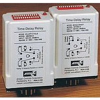
Time Delay Relay
www.artisancontrols.com
MODE : DELAY ON MAKE
MODEL : 2411SA-8
INPUT : 120VAC, 50/60Hz
RANGE : 0.1 SEC - 1024 HRS
Tel: 973-598-9400 • Fax: 973-598-9410 • Toll Free: 800-457-4950
Artisan Controls Corporation, 111 Canfield Ave. Bldg B15-18, Randolph, New Jersey 07869, USA
5
4
2.4 MAX
6
3
7
Made in USA
2
8
1
0.1 0.2 0.4 0.8 1.6 3.2 6.4 12.8 25.6 51.2
DIP Switch Chart . . . . . . . . . . . . . . . . . . . . . . . . . . . . . . . . . . .
1
1
1
1
V
Voltage
Input
Solid State Timers and Controllers
I S I T O U R W E B S I T E A T
2
2
2
2
0.6 MAX
1.8 MAX
3.6 MAX
3
4
4
4
4
8
8
8
Timing Diagram . . . . . . . . . . . . . . . . . . . . . . . . . . . . . . . . . . .
Setting the Time Delay . . . . . . . . . . . . . . . . . . . . . . . . . . . . .
2411SA
The 2411SA is an initiate switch controlled delay on make timer
controlling a SPDT set of relay contacts. The 2411SA is available in both
AC and DC voltage models, and all models provide an integral 12 position
DIP switch used to determine the time delay value. With the operating
voltage applied the unit is in standby mode. Closure of the Initiate Switch
begins the time delay, at the of which the output contacts transfer.
Opening the switch de-energizes the output contacts. DIP switches 11 &
12 determine the time delay range, while switches 1 - 10 determine the
time delay period. The integral LED indicates the state of the output
contacts.
Operating
Voltage
Initiate
Switch
Output
Contacts
Setting the time delay is an easy two step process :
Selecting the Time Range - Open or Close switches 11 & 12 per the chart
below to select from the four time ranges: 0.1 - 102.4 seconds, 1 - 1024
seconds, 1 - 1024 minutes, and 1 - 1024 hours.
Setting the Time Delay - The timer has a built-in delay equal to the switch
1 value for the selected range (0.1 sec, 1 sec, etc.). Close the additional
switches (1 - 10) which add their values from the chart below to the built-
in time to achieve the desired time delay.
Example: To set for 30 minutes - switches 11 closed and 12 open for
minutes range, then close switches 5, 4, 3, and 1 for a total of 29 minutes,
all other switches open. The built in 1 minute completes the full 30 minutes.
16
16
16
5
32
32
32
6
OPEN
64 128 256 512
64 128 256 512
64 128 256 512
OFF
7
8
DELAY
: www.artisancontrols.com
ON
9
10
ON
ON ON
CLOSED
11
off
off
DIP Switch Adjustable
ON
Delay On Make Timer
ON
12
off
off
0.1 - 102.4 Seconds
Time Delay Range
1 - 1024 Seconds
1 - 1024 Minutes
1 - 1024 Hours
DELAY
Related parts for 2411SA-8
Image
Part Number
Description
Manufacturer
Datasheet
Request
R

Part Number:
Description:
CONTROLLERS,TYPE 4950 7-DAY PROGRAMMABLE CONTROLLERS,CONTROLLERS,PHOTOMOS RELAY,CONTROLLERS,4950 SERIES 7-DAY PROGRAMMABLE CONTROLLERS ,ARTISAN CONTROLS
Manufacturer:
ARTISAN CONTROLS
Datasheet:

Part Number:
Description:
SOLID STATE TIMER, DPDT, 1024H, 115VAC
Manufacturer:
ARTISAN CONTROLS
Datasheet:
Part Number:
Description:
SOLID STATE TIMER, SPDT, 1024H, 115VAC
Manufacturer:
ARTISAN CONTROLS
Datasheet:
Part Number:
Description:
SOLID STATE TIMER, DPDT, 1024H, 115VAC
Manufacturer:
ARTISAN CONTROLS
Datasheet:

Part Number:
Description:
SOLID STATE FLASHER, 60FPM, 115VAC
Manufacturer:
ARTISAN CONTROLS
Datasheet:

Part Number:
Description:
SOLID STATE FLASHER, 60FPM, 24VDC
Manufacturer:
ARTISAN CONTROLS
Datasheet:

Part Number:
Description:
SOLID STATE TIMER, 30SEC, 12VDC
Manufacturer:
ARTISAN CONTROLS
Datasheet:
Part Number:
Description:
SOLID STATE TIMER, 30SEC, 24VDC
Manufacturer:
ARTISAN CONTROLS
Datasheet:
Part Number:
Description:
SOLID STATE TIMER, 30SEC, 120VAC
Manufacturer:
ARTISAN CONTROLS
Datasheet:

Part Number:
Description:
SOLID STATE TIMER SPST-NO, 30SEC, 120VAC
Manufacturer:
ARTISAN CONTROLS
Datasheet:
Part Number:
Description:
SOLID STATE TIMER SPST-NO 300SEC, 120VAC
Manufacturer:
ARTISAN CONTROLS
Datasheet:

Part Number:
Description:
SOLID STATE TIMER, 1SEC, 110VDC
Manufacturer:
ARTISAN CONTROLS
Datasheet:

Part Number:
Description:
SOLID STATE TIMER, 1024SEC, 240VAC
Manufacturer:
ARTISAN CONTROLS
Datasheet:

Part Number:
Description:
SOLID STATE TIMER, 30SEC, 115VAC/DC
Manufacturer:
ARTISAN CONTROLS
Datasheet:

Part Number:
Description:
Controller; PCB Mount; Screw; SPDT; 115 VAC; 1.625 in.; 0 to 70 degC
Manufacturer:
ARTISAN CONTROLS
Datasheet:
2411SA-8 Summary of contents
Page 1
... Solid State Timers and Controllers 0.1 Seconds to 1024 Hours ! 1.8 MAX 2.4 MAX Time Delay Relay MODE : DELAY ON MAKE MODEL : 2411SA-8 INPUT : 120VAC, 50/60Hz RANGE : 0.1 SEC - 1024 HRS Start Switch Input Voltage 3.6 MAX Artisan Controls Corporation Parsippany, NJ Made in USA www ...
Page 2
... Ordering Information . . . . . . . . . . . . . . . . . . . . . . . . . . . . . . . . . . . . . . . . . . . . . . . . . . . . . . Model Number Operating Voltage -2 (12V DC) 2411SA -3 (24V AC/DC) -8 (120V AC) Typical Wiring Example . . . . . . . . . . . . . . . . . . . . . . . . . . . . . . . . . . . . . . . . . . . . . . . . . . . . . . . . . . ...