RJ1P23MBT50ECS CARLO GAVAZZI, RJ1P23MBT50ECS Datasheet - Page 5
RJ1P23MBT50ECS
Manufacturer Part Number
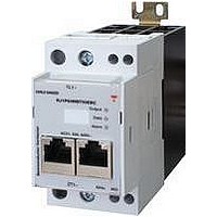
RJ1P23MBT50ECS
Description
SSR, DIN RAIL MOUNT, 265VAC, 30VDC, 50A
Manufacturer
CARLO GAVAZZI
Datasheet
1.RJ1P23MBT50EBC.pdf
(5 pages)
Specifications of RJ1P23MBT50ECS
Control Voltage Type
AC
Control Voltage Range
19.2VDC To 30VDC
Operating Voltage Range
90VAC To 265VAC
Peak Surge Current
1.9kA
Load Current
50A
Switching Mode
Proportional Output


Specifications are subject to change without notice (30.03.2007)
Mode 0 – ON/OFF control
In Mode 0 the relay operates as
a standard ON/OFF relay with
zero switching. In this mode
the relay can deliver either 0%
or 100% power. This mode is
ideal for systems where the
process controller employs a
digital process variable, similar
to that used in standard solid
state relay applications.
RJ1P MB
Connection Examples
Notes:
1. A terminating resistor (value 100
2. 24V power may be applied through terminals 6A4, 4A2 or through the RJ-45 connector. If daisy chaining several devices using standard ethernet patch leads, the
3. Max. no of daisy chained devices may be limited by patch-lead conductor diameter and length.
4. Refer to product handbook for detailed installation instructions.
Operation
connection to 6A4, 4A2 is optional for the second and successive devices. For large networks it is necessary to connect 6A4, 4A2 every 25th device.
RS485 from
PLC/IPC
to 130
Mode 1 – Phase angle control
In Mode 1 the load power is
adjusted by delaying the thyris-
tor switching signal according
to the required power.
resulting output is a chopped
sine-wave. The relay switches
itself off every half cycle.
Timings are calculated such
that a linear power response
curve is obtained. This mode
is suited for loads where con-
tinuous control of power is
required.
) must be fitted at each end of the RS485 network.
The
Mode 2 – Distributed firing
In Mode 2 full cycles are
switched ON/OFF over a peri-
od of 256 mains cycles. The
number of cycles that are
switched ON corresponds to
the value specified in the load
power register.
uses an algorithm that distrib-
utes the ON cycles evenly over
the 256 cycle period.
This mode
Mode 3 – Burst firing
In Mode 3 full cycles are
switched ON/OFF over a peri-
od of mains cycles as defined
by the Time-Base Register.
Mode 3 uses an algorithm that
will switch ON a number of
cycles in a continuous burst for
a time period corresponding to
the required power.
To other devices or
terminating resistor
5
Related parts for RJ1P23MBT50ECS
Image
Part Number
Description
Manufacturer
Datasheet
Request
R

Part Number:
Description:
MAGNETIC CYLINDRICAL PROX. SENSOR
Manufacturer:
CARLO GAVAZZI
Datasheet:
Part Number:
Description:
CYLINDRICAL MAGNETIC SENSOR
Manufacturer:
CARLO GAVAZZI
Datasheet:
Part Number:
Description:
MAGNETIC CYLINDRICAL PROX. SENSOR
Manufacturer:
CARLO GAVAZZI
Datasheet:
Part Number:
Description:
Current and Voltage Controls / Current Transformer / 3-Phase
Manufacturer:
Carlo Gavazzi
Datasheet:

Part Number:
Description:
Definite Purpose Contactor
Manufacturer:
CARLO GAVAZZI
Datasheet:
Part Number:
Description:
Definite Purpose Contactor
Manufacturer:
CARLO GAVAZZI
Datasheet: