704.901.4 EAO, 704.901.4 Datasheet - Page 56
704.901.4
Manufacturer Part Number
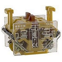
704.901.4
Description
SWITCHING ELEMENT, 2NC, 10A, SCREW
Manufacturer
EAO
Datasheet
1.704.066.2.pdf
(85 pages)
Specifications of 704.901.4
No. Of Poles
2
Contact Current Max
10A
Contact Voltage Ac Max
500V
Contact Voltage Dc Max
110V
Switch Terminals
Screw
Leaded Process Compatible
Yes
Circuitry
2NC
Rohs Compliant
Yes
For Use With
04 Series Switches
Lead Free Status / RoHS Status
Lead free / RoHS Compliant


technical data
switching system
material
mechanical characteristics
slow-make switching element
switching system
The double-break, slow-make switching element is equipped with
one or two independent contact systems, acting as normally open
or normally closed contact.
Slow-make contacts with forced action are ideal for high switch ra-
tings. Up to 3 switching elements can be snapped to each actuator.
Up to 3 switching elements can be snapped to each actuator.
material of contacts
hardsilver, gold/silver, silver/palladium (for aggressive atmosphe-
res)
switching element
polycarbonate PC
connection method
screw terminals
plug-in terminals 6.3 x 0.8 mm:
max. wire cross-section: 2 x 2.5 mm&
max. wire cross-section of stranded cable: 2 x 1.5 mm&.
For switches with plug-in terminals it is necessary to provide insula-
tion sockets and to maintain a spacing of 65 mm between rows
(mounting dimensions).
starting torque
screws at the mounting flange: max. 25 Ncm
screws at switching element: max. 50 Ncm
actuating force
13-36 N
depending on the number of switching elements, 1 to 3 elements
storage temperature
-40°C to + 85°C
mechanical life
pushbuttons:
maintained action 1.5 million cycles of operation
momentary action 3 million cycles of operation
selector switch:
maintained action 1.25 million cycles of operation
momentary action 2.5 million cycles of operation
emergency stop switch: >= 50´000 cycles of operation
key lock switch:
maintained action 25´000 cycles of operation
momentary action 50´000 cycles of operation"
travel
5.8
resistance to shock
(single impacts, semi-sinusoidal)
30 g for 11 ms as per EN 60 947-5-1
resistance to vibration
(sinusoidal)
10 g at 10-2000 Hz, amplitude 0,75 mm as per EN 60 947-5-1
rebound time
<= 1 ms
0.2 mm
1 N
electrical characteristics
0
0
0
0
approvals
ambient air temperature
min. - 25°C (- 40° with restriction)
max. without illumination: + 80°C
max. with neon lamp + 80°C
max. with LED: + 80°C
max. with incandescent lamp: + 40°C
rated insulation voltage
500 VAC/600 VDC as per VDE 0100, group C
standards
The switches comply with the Rules for low-voltage switching de-
vices" EN 60 947-5-1
contact resistance
starting value <= 50 m
insulation resistance
>= 100 M
10.
continuous thermal current lth
10 A
The maximum current in continuous operation and at ambient tem-
perature must not exceed the quoted maximum values.
switch rating max.
at switch rating AC for gold-, silver- and hard silver contacts service
category AC-15 as per EN60947-5-1
(cos
voltage:
current:
at switch rating DC for gold-, silver- and hard silver contacts service
category DC as per EN60947-5-1
L/R=100 ms at P>=50 W and
L/R=2 x P ms<50 W
WOP stands for switch rating in watt
voltage:
current:
switch rating min.
gold/silver contacts:
voltage
current:
hard silver contakts:
voltage
current:
electric strength
5000 VAC, 50 Hz, 1 min. between all terminals and earth
approvals
- SEV 500 VAC/10 A
- CSA 300 VAC
- UL 600 VAC HD
- German Navy SAK page no.3337 on request
- German Lloyd
- CE (declaration of conformity)
- CB
= 0.7)
between open contacts at 500 VDC, as per IEC 512-2-
230 VAC
7 A
24 VDC
10 A
24 VDC
10 mA
24 VDC
50 mA
as per IEC 512-2-4
2
400 VAC
5 A
60 VDC
5 A
110 VDC
2 mA
110 VDC
10 mA
01.2002
119
500 VAC
4 A
110 VDC
2.5 A
04
Related parts for 704.901.4
Image
Part Number
Description
Manufacturer
Datasheet
Request
R

Part Number:
Description:
SWITCHING ELEMENT, 1NC, 10A, SCREW
Manufacturer:
EAO
Datasheet:

Part Number:
Description:
CONTACT BLOCK, 2NO
Manufacturer:
EAO
Datasheet:
Part Number:
Description:
CONTACT BLOCK, 1NO/1NC
Manufacturer:
EAO
Datasheet:

Part Number:
Description:
SWITCHING ELEMENT, 2NC, 10A, SCREW
Manufacturer:
EAO
Datasheet:

Part Number:
Description:
Indicator
Manufacturer:
EAO
Datasheet:


Part Number:
Description:
SINGLE CHIP LED/ T1 BI-PIN/ 2.1VDC/20MA - RED
Manufacturer:
EAO
Datasheet:

Part Number:
Description:
INDICATOR, INCAND LAMP, BI PIN
Manufacturer:
EAO
Datasheet:

Part Number:
Description:
INDICATOR, BI-PIN
Manufacturer:
EAO
Datasheet:

Part Number:
Description:
INDICATOR, INCAND LAMP, MIDGET GROOVED
Manufacturer:
EAO
Datasheet: