704.901.4 EAO, 704.901.4 Datasheet - Page 57
704.901.4
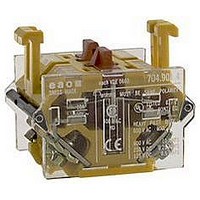
Manufacturer Part Number
704.901.4
Description
SWITCHING ELEMENT, 2NC, 10A, SCREW
Manufacturer
EAO
Datasheet
1.704.066.2.pdf
(85 pages)
Specifications of 704.901.4
No. Of Poles
2
Contact Current Max
10A
Contact Voltage Ac Max
500V
Contact Voltage Dc Max
110V
Switch Terminals
Screw
Leaded Process Compatible
Yes
Circuitry
2NC
Rohs Compliant
Yes
For Use With
04 Series Switches
Lead Free Status / RoHS Status
Lead free / RoHS Compliant


technical data
buzzer system
material
mechanical characteristics
electrical characteristics
0
material
mechanical characteristics
buzzer
actuator
system
Piezo disc
alarm buzzer case
polyamide
front cap
plastic: polyamide
metal: nickel-plated brass
connection method
plug-in terminal 2.8 x 0.5 mm
operating temperature
-25°C to + 50°C
storage temperature
-25°C to + 50°C
degree of protection
IP 65 (raised fitting) as per IEC 529
frequency (tone)
ca. 2.8 kHz continuous tone only
sound pressure
95 db (A)
operation voltage/current
operation voltage:
operation current:
front ring
polyamide, aluminium or chromium-plated nickel steel
mounting flange
polyethylene terephtalate
actuator case
polycarbonate, polyamide
actuating force
snap-action switching element: 11-20 N
slow-make switching element: 13-36 N
depending on the number of snap-action elements
storage temperature
-30°C to + 85°C
IP 40 as per IEC 529 (flush mounting)
sea-water proof
120
01.2002
8 at a distance of 0.1 m
t24 VDC
<= 25 mA
1 N
1 N
10%
electrical characteristics
mechanical characteristics
electrical characteristics
rotary selector switch element
mechanical life
pushbutton: >= 3 million operations
selector switch: >= 2.5 million operations
Emergency stop switch: >= 50´000 operations
keylock switch: >= 50´000 operations
travel
5.8
degree of protection
front as per IEC 529: IP 65
ambient air temperature
min. -25°C
max. without illumination: + 80°C
max. with neon lamp: + 80°C
max. with LED: + 80°C
max. with incandescent lamp: + 55°C
standards
The switches comply with the "Rules for low-voltage switching de-
vices" EN 60 947-5-1
number of positions
1 to 8 positions max.
number of contacts
1 to 16 max. normally open contacts
(contact positioning to the rotary plan)
switching angle
Switching position a (9
maintained action switching angle
12 x 30° max.
8 x 45° max.
6 x 60° max.
4 x 90° max.
momentary action with release 24°
(provide at the beginning or at the end )
standard type of Kraus + Naimer
- CG 4
- CG 4-1 hardsilver contacts with 35
DC 1, resistive circuits T = 1 ms
1 contact in line
permissible voltage 24 V
rated service current l 10.0 A 6.0 A 2.5 A 0.7 A
2 contacts in line
permissible voltage 48 V
rated service current l 10.0 A 6.0 A
3 contacts in line
permissible voltage 70 V
rated service current l 10.0 A 6.0 A
4 contacts in line
permissible voltage 95 V
rated service current l 10.0 A 6.0 A
5 contacts in line
permissible voltage 120 V
rated service current l 10.0 A
0.2 mm
hardsilver contacts with 1
00
) is basic position
48 V
95 V
140 V
190 V
240 V
6.0 A
60 V 110 V 220 V 440 V
120 V 220 V 440 V 660 V
180 V 330 V 660 V
240 V 440 V
300 V
gold layer
2.5 A 0.7 A
gold layer
2.5 A
2.5 A
2.5 A
550 V
0.7 A
0.7 A
0.7 A
0.3 A
0.3 A
0.3 A
04
0.2 A
0.2 A
Related parts for 704.901.4
Image
Part Number
Description
Manufacturer
Datasheet
Request
R

Part Number:
Description:
SWITCHING ELEMENT, 1NC, 10A, SCREW
Manufacturer:
EAO
Datasheet:

Part Number:
Description:
CONTACT BLOCK, 2NO
Manufacturer:
EAO
Datasheet:
Part Number:
Description:
CONTACT BLOCK, 1NO/1NC
Manufacturer:
EAO
Datasheet:

Part Number:
Description:
SWITCHING ELEMENT, 2NC, 10A, SCREW
Manufacturer:
EAO
Datasheet:

Part Number:
Description:
Indicator
Manufacturer:
EAO
Datasheet:


Part Number:
Description:
SINGLE CHIP LED/ T1 BI-PIN/ 2.1VDC/20MA - RED
Manufacturer:
EAO
Datasheet:

Part Number:
Description:
INDICATOR, INCAND LAMP, BI PIN
Manufacturer:
EAO
Datasheet:

Part Number:
Description:
INDICATOR, BI-PIN
Manufacturer:
EAO
Datasheet:

Part Number:
Description:
INDICATOR, INCAND LAMP, MIDGET GROOVED
Manufacturer:
EAO
Datasheet: