AEDB-9140-E11 Avago Technologies US Inc., AEDB-9140-E11 Datasheet - Page 2
AEDB-9140-E11
Manufacturer Part Number
AEDB-9140-E11
Description
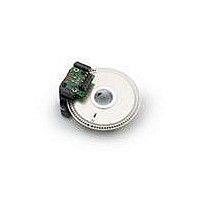
MOD ENCODER 3CH 200CPR 28MM 4MM
Manufacturer
Avago Technologies US Inc.
Series
AEDB-9140r
Datasheet
1.AEDB-9140-A04.pdf
(9 pages)
Specifications of AEDB-9140-E11
Pulses Per Revolution
200
Encoder Type
Optical
Output Type
Quadrature with Index (Incremental)
Voltage - Supply
5VDC
Actuator Type
4mm Open Center
Detent
No
Built In Switch
No
Mounting Type
Chassis Mount, Motors
Termination Style
Terminal Pins
Number Of Channels
3
Supply Voltage
5 V
Product
Optical
Lead Free Status / RoHS Status
Lead free / RoHS Compliant
Orientation
-
Rotational Life (cycles Min)
-
Lead Free Status / Rohs Status
Lead free / RoHS Compliant


Ordering Information
Three Channel Encoder Modules with Codewheel, 11 mm Optical Radius
* Please contact factory for other shaft diameters
Available Options
2
Part No
AEDB-9140
AEDB-9140 Option
Resolutions
(Cycle/Rev)
C - 100 CPR
E - 200 CPR
F - 256 CPR
G - 360 CPR
H - 400 CPR
A - 500 CPR
CPR
C
E
F
G
H
A
Shaft Diameter Options
02
•
04
•
•
•
Shaft Diameter*
02 - 3mm
04 - 5/32 in
05 - 3/16 in
06 - 1/4 in
11 - 4mm
12 - 6mm
13 - 8mm
14 - 5mm
05
•
06
•
•
•
•
•
11
•
•
12
•
•
•
•
•
13
•
•
14
•
•
•
•
•
Theory of Operation
The AEDB-9140 are emitter/detector
modules. Coupled with a codewheel,
these modules translate the rotary
motion of a shaft into a three-chan-
nel digital output.
As seen in Figure 1, the modules
contain a single Light Emitting Diode
(LED) as its light source. The light is
collimated into a parallel beam by
means of a single polycarbonate lens
located directly over the LED. Op-
posite the emitter is the integrated
detector circuit. This IC consists of
multiple sets of photodetectors
and the signal processing circuitry
necessary to produce the digital
waveforms.
The codewheel rotates between the
emitter and detector, causing the
light beam to be interrupted by the
pattern of spaces and bars on the
codewheel.
The photodiodes which detect these
interruptions are arranged in a pat-
tern that corresponds to the radius
and design of the code-wheel. These
detectors are also spaced such that a
light period on one pair of detectors
corresponds to a dark period on the
adjacent pair of detectors.
The photodiode outputs are then
fed through the signal processing
circuitry resulting in A, Abar, B, Bbar,
I and Ibar. Comparators receive these
signals and produce the fi nal outputs
for channels A and B. Due to this inte-
grated phasing technique, the digital
output of channel A is in quadrature
with that of channel B (90 degrees
out of phase).
Related parts for AEDB-9140-E11
Image
Part Number
Description
Manufacturer
Datasheet
Request
R

Part Number:
Description:
MOD ENCODER 3CH 500CPR 28MM 5/32
Manufacturer:
Avago Technologies US Inc.
Datasheet:
Part Number:
Description:
MOD ENCODER 3CH 500CPR 28MM 3/16
Manufacturer:
Avago Technologies US Inc.
Datasheet:
Part Number:
Description:
MOD ENCODER 3CH 100CPR 28MM 1/4"
Manufacturer:
Avago Technologies US Inc.
Datasheet:
Part Number:
Description:
MOD ENCODER 3CH 100CPR 28MM 6MM
Manufacturer:
Avago Technologies US Inc.
Datasheet:
Part Number:
Description:
MOD ENCODER 3CH 100CPR 28MM 8MM
Manufacturer:
Avago Technologies US Inc.
Datasheet:
Part Number:
Description:
MOD ENCODER 3CH 200CPR 28MM 1/4"
Manufacturer:
Avago Technologies US Inc.
Datasheet:
Part Number:
Description:
MOD ENCODER 3CH 256CPR 28MM 5/32
Manufacturer:
Avago Technologies US Inc.
Datasheet:

Part Number:
Description:
En,6Ch,1000CPR,G CW,29mm,2pp, 8mm
Manufacturer:
Avago Technologies US Inc.
Datasheet:
Part Number:
Description:
En,6Ch,1000CPR,G CW,29mm,4pp,8mm
Manufacturer:
Avago Technologies US Inc.
Datasheet:
Part Number:
Description:
En,6Ch,1024CPR,G CW,29.4mm,2pp,8mm
Manufacturer:
Avago Technologies US Inc.
Datasheet:

Part Number:
Description:
OPTOCOUPLER GATE DRV 2A 16-SOIC
Manufacturer:
Avago Technologies US Inc.
Datasheet:
Part Number:
Description:
OPTOCOUPLER 2CH 2.5A 16-SOIC
Manufacturer:
Avago Technologies US Inc.
Datasheet:

Part Number:
Description:
OPTOCOUPLER GATE DRV 0.4A 16SOIC
Manufacturer:
Avago Technologies US Inc.
Datasheet:

Part Number:
Description:
OPTOCOUPLER 2.0A 250KHZ 8-DIP
Manufacturer:
Avago Technologies US Inc.
Datasheet:

Part Number:
Description:
OPTOCOUPLER 2.0A 250KHZ GW 8-SMD
Manufacturer:
Avago Technologies US Inc.
Datasheet: