AS5245-HQFT-500 austriamicrosystems, AS5245-HQFT-500 Datasheet
AS5245-HQFT-500
Specifications of AS5245-HQFT-500


Related parts for AS5245-HQFT-500


AS5245-HQFT-500 Summary of contents
Page 1
... Fully automotive qualified to AEC-Q100, grade 0 Small package: QFN 32 LD (7x7) 3 Applications The AS5245 is ideal for applications with an angular travel range from a few degrees full turn of 360º. The device is suitable for Automotive applications like Throttle position sensors, Gas/brake pedal position sensing, Headlight position control, Contactless rotary position sensing, Front panel rotary switches and Replacement of potentiometer ...
Page 2
... Power Supply Failure Detection ................................................................................................................................................ 23 9.6 Angular Output Tolerances ................................................................................................................................................................. 23 9.6.1 Accuracy .................................................................................................................................................................................... 23 9.6.2 Transition Noise......................................................................................................................................................................... 25 9.6.3 High Speed Operation ............................................................................................................................................................... 25 9.6.4 Propagation Delays ................................................................................................................................................................... 26 9.6.5 Internal Timing Tolerance .......................................................................................................................................................... 26 9.6.6 Temperature .............................................................................................................................................................................. 26 9.6.7 Accuracy over Temperature ...................................................................................................................................................... 26 9.7 AS5245 Differences to AS5045.......................................................................................................................................................... 27 10 Package Drawings and Markings ......................................................................................................................................... 11 Ordering Information ............................................................................................................................................................. www.austriamicrosystems.com/AS5245 Revision 1 ...
Page 3
... AS5245 Data Sheet - Pin Assignments Figure 2. Pin Assignments (Top View) DTest1_A_Bottom DTest2_B_Top DTest2_B_Bottom NC NC Mode_Index_Top Mode_Index_Bottom VSS_Top www.austriamicrosystems.com/AS5245 AS5245 Revision 1.5 24 VDD3V_Bottom PWM_Top 18 PWM_Bottom 17 CSn_Top ...
Page 4
... VDD3V3 24, 25 VDD5V 26, 27 MagINCn 28, 29 MagDECn 30, 31 www.austriamicrosystems.com/AS5245 Pin Type Test output in default mode Digital output Test output in default mode Digital output For internal use. Must be left unconnected - Select between slow (open, low: VSS) and fast (high) mode. Internal pull- Digital I/O pull-down down resistor ...
Page 5
... Table 2. Absolute Maximum Ratings Parameter DC supply voltage at pin VDD5V DC supply voltage at pin VDD3V3 Input pin voltage Input current (latchup immunity) Electrostatic discharge Storage temperature Body temperature (Lead-free package) Humidity non-condensing Ambient temperature www.austriamicrosystems.com/AS5245 Electrical Characteristics on page 6 Min Max Units -0 -0 -0.3 ...
Page 6
... Low level input voltage IL I High level input current iL DC Characteristics CMOS Output Open Drain: MagINCn, MagDECn I Open drain leakage current OZ V Low level output voltage OL www.austriamicrosystems.com/AS5245 Condition (one die only Operation 5V DD 3.3V Operation (pin V 5V and V 3V3 connected) 3V3 ...
Page 7
... VDD5V = 4.5 to 5.5V (5V operation) unless otherwise noted. AMB DD Table 4. Input Specification Symbol Parameter RES Resolution INL Integral non-linearity (optimum) opt INL Integral non-linearity (optimum) temp INL Integral non-linearity DNL Differential non-linearity TN Transition noise www.austriamicrosystems.com/AS5245 Condition V 5V 5V 5V 5V: 4 ...
Page 8
... Integral Non-Linearity (INL) is the maximum deviation between actual position and indicated position. Differential Non-Linearity (DNL) is the maximum deviation of the step length from one position to the next. Transition Noise (TN) is the repeatability of an indicated position. www.austriamicrosystems.com/AS5245 Condition Fast mode (Mode = 1); Until status bit OCF = 1 Slow mode (Mode = 0 or open) ...
Page 9
... LOAD frequency LOAD f READ frequency READ f WRITE frequency WRITE www.austriamicrosystems.com/AS5245 Conditions Min Time between falling edge of CSn and data output activated Time between falling edge of CSn and 500 first falling edge of CLK Rising edge of CLK shifts out one bit at a 500 ...
Page 10
... The AS5245 senses the orientation of the magnetic field and calculates a 12-bit binary code. This code can be accessed via. a Synchronous Serial Interface (SSI). In addition, an absolute angular representation is given by a Pulse Width Modulated signal at pin 12 (PWM). This PWM signal output also allows the generation of a direct proportional analog voltage, by using an external Low-Pass-Filter ...
Page 11
... Even Parity – Bit for transmission error detection of bits 1…17 (D11…D0, OCF, COF, LIN, MagINC, MagDEC). Placing the magnet above the chip, angular values increase in clockwise direction by default. Data D11:D0 is valid, when the status bits have the following configurations: Table 7. Status Bit Outputs OCF COF 1 0 Note: MagInc=MagDec=1 is only recommended in YELLOW mode www.austriamicrosystems.com/AS5245 ...
Page 12
... Incremental Mode The AS5245 has an internal interpolator block. This function is used if the input magnetic field is too fast and a code position is missing. In this case an interpolation is done. With the OTP bits OutputMd0 and OutputMd1 a specific mode can be selected. For the available pre-programmed incremental versions (10bit and 12bit), these bits are set during test at austriamicrosystems ...
Page 13
... LSB, until position “x+2“is reached. Following this direction, the incremental outputs will again be updated with every change of the magnet position. Figure 7. Hysteresis Window for Incremental Outputs Incremental Output Indication www.austriamicrosystems.com/AS5245 Programmed Zero Position 1 LSB 3 LSB Hysteresis : 0.35° ...
Page 14
... Daisy Chain Mode The Daisy Chain mode allows connection of several AS5245s in series, while still keeping just one digital input for data transfer (see “Data IN” in Figure 9). This mode is accomplished by connecting the data output (DO; pin 9) to the data input (PDIO; pin 8) of the subsequent device. The serial data of all connected devices is read from the DO pin of the first device in the chain ...
Page 15
... DO active 8.3 Pulse Width Modulation (PWM) Output The AS5245 provides a pulse width modulated output (PWM), whose duty cycle is proportional to the measured angle. For angle position 0 to 4094: Examples angle position of 180º will generate a pulse width ton = 2049µs and a pause t calculation: 2049 * 4098 / (2049 + 2049 2048 2. An angle position of 359.8º ...
Page 16
... AS5245 Data Sheet - 8.3.1 Changing the PWM Frequency The PWM frequency of the AS5245 can be divided by two by setting a bit (PWMhalfEN) in the OTP register page 17). With PWMhalfEN = 0, the PWM timing is as shown in Table 10. PWM Signal Parameters (Default mode) Symbol Parameter f PWM frequency PWM ...
Page 17
... After power-on, programming the AS5245 is enabled with the rising edge of CSn with PDIO = high and CLK = low. The AS5245 programming is a one-time programming (OTP) method, based on poly silicon fuses. The advantage of this method is that a programming voltage of only 3.3V to 3.6V is required for programming. ...
Page 18
... User Selectable Settings The AS5245 allows programming of the following user selectable options: - PWMhalfEN_Indexwidth: Setting this bit, the PWM pulse will be divided case of quadrature incremental mode A/B/Index setting of Index impulse width from 1 LSB to 3LSB. - MagCompEN: The green/yellow mode can be enabled by setting of this bit. ...
Page 19
... AS5245 Data Sheet - 9.1.4 OTP Default Setting The AS5245 can also be operated without programming. The default, un-programmed setting is: - Output Md0, Output MD1: 00= Default mode - Z0 to Z11 programmed zero position - CCW clockwise operation - RA4 to RA0 OTP bit is selected - MagCompEN The green / yellow mode is enabled. ...
Page 20
... The Alignment mode can be reset to normal operation by a power-on-reset (disconnect / re-connect power supply falling edge on CSn with PDIO = low. Figure 13. Enabling the Alignment Mode PDIO CSn Figure 14. Exiting Alignment Mode PDIO CSn www.austriamicrosystems.com/AS5245 (see Figure AlignMode enable 2µs 2µs min. min. exit AlignMode Revision 1 ...
Page 21
... Data Sheet - 9.3 3. Operation The AS5245 operates either at 3.3V ±10 ±10%. This is made possible by an internal 3.3V Low-Dropout (LDO) Voltage regulator. The internal supply voltage is always taken from the output of the LDO, meaning that the internal blocks are always operating at 3.3V. ...
Page 22
... The magnetic field strength perpendicular to the die surface has the range of ±45mT…±75mT (peak). The magnet’s field strength should be verified using a gauss-meter. The magnetic field B radius of 1.1mm (R1), should be in the range of ±45mT…±75mT Figure 16. Typical Magnet (6x3mm) and Magnetic Field Distribution www.austriamicrosystems.com/AS5245 at a given distance, along a concentric circle with a v (see Figure 16) ...
Page 23
... Power Supply Failure Detection By Software: If the power supply to the AS5245 is interrupted, the digital data read by the SSI will be all “0”s. Data is only valid, when bit OCF is high, hence a data stream with all “0”s is invalid. To ensure adequate low levels in the failure case, a pull-down resistor (~10kΩ) should be added between pin DIO and VSS at the receiving side ...
Page 24
... IC within the package (±0.235mm) must also be taken into account. The total nonlinearity error over process tolerances, temperature and a misalignment circle radius of 0.25mm is specified better than ±1.4 degrees. The magnet used for this measurement was a cylindrical NdFeB (Bomatec® BMN-35H) magnet with 6mm diameter and 2.5mm in height. www.austriamicrosystems.com/AS5245 -400 -700 ...
Page 25
... High Speed Operation Sampling Rate. The AS5245 samples the angular value at a rate of 2.61k (slow mode) or 10.42k (fast mode, selectable by pin MODE) samples per second. Consequently, the absolute outputs are updated each 384µs (96µs in fast mode stationary position of the magnet, the sampling rate creates no additional error ...
Page 26
... Internal Timing Tolerance The AS5245 does not require an external ceramic resonator or quartz. All internal clock timings for the AS5245 are generated by an on-chip RC oscillator. This oscillator is factory trimmed to ±5% accuracy at room temperature (±10% over full temperature range). This tolerance influences the ADC sampling rate and the pulse width of the PWM output: Absolute Output ...
Page 27
... This influence, however, can be cancelled by measuring the complete PWM duty cycle instead of just the PWM pulse. 9.7 AS5245 Differences to AS5045 All parameters are according to AS5045 data sheet except for the parameters shown below: Table 14. Difference Between AS5245 and AS5045 Building Block 12bits, 0.088º/step. ...
Page 28
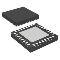
... The device is available in a QFN 32 (7mm x 7mm) package. Figure 19. Package Drawings AS5245 Top View Side View Table 15. Package Dimensions Symbol Min 4.18 E1 4.18 L 0. 0.80 A1 www.austriamicrosystems.com/AS5245 Bottom View mm Typ Max Min 7 BSC 7 BSC 4.28 4.38 0.165 4.28 4.38 0.165 0.55 0.65 0.018 0.30 ...
Page 29
... Nov 05, 2009 1.3 Dec 04, 2009 Apr 01, 2010 1.4 Apr 13, 2010 1.5 Jun 17, 2010 Note: Typos may not be explicitly mentioned under revision history. www.austriamicrosystems.com/AS5245 Owner Initial revision Changes made to values in Table 9 apg Updated min, typ, max values for t Characteristics 1) Note added under ...
Page 30
... Note: All products are RoHS compliant and Pb-free. Buy our products or get free samples online at ICdirect: For further information and requests, please contact us or find your local distributor at http://www.austriamicrosystems.com/distributor www.austriamicrosystems.com/AS5245 Table 16. Description Delivery Form Tape & Reel http://www ...
Page 31
... No obligation or liability to recipient or any third party shall arise or flow out of austriamicrosystems AG rendering of technical or other services. Contact Information Headquarters austriamicrosystems AG Tobelbaderstrasse 30 A-8141 Unterpremstaetten, Austria Tel: +43 (0) 3136 500 0 Fax: +43 (0) 3136 525 01 For Sales Offices, Distributors and Representatives, please visit: http://www.austriamicrosystems.com/contact www.austriamicrosystems.com/AS5245 Revision 1 ...