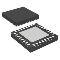
AS5245-HQFT-500 austriamicrosystems, AS5245-HQFT-500 Datasheet - Page 12

AS5245-HQFT-500
Manufacturer Part Number
AS5245-HQFT-500
Description
IC ENCODER ROTARY 32-QFN
Manufacturer
austriamicrosystems
Type
Linear, Rotary Encoder - Programmabler
Datasheet
1.AS5245-HQFT-500.pdf
(31 pages)
Specifications of AS5245-HQFT-500
Featured Product
AS5245 â Dual Die Motion Sensing IC
Sensing Range
45mT ~ 75mT
Voltage - Supply
3 V ~ 3.6 V, 4.5 V ~ 5.5 V
Current - Supply
21mA
Current - Output (max)
4mA
Output Type
Quadrature with Index (Incremental)
Features
Programmable
Operating Temperature
-40°C ~ 150°C
Package / Case
32-VQFN Exposed Pad
Lead Free Status / RoHS Status
Lead free / RoHS Compliant
Other names
AS5245-HQFT-500TR
AS5245
Data Sheet - D e t a i l e d D e s c r i p t i o n
8.2.2 Z-axis Range Indication (Push Button Feature, Red/Yellow/Green Indicator)
The AS5245 provides several options of detecting movement and distance of the magnet in the Z-direction. Signal indicators MagINCn and
MagDECn are available both as hardware pins (pins #1 and 2) and as status bits in the serial data stream
programming option is available with bit MagCompEn that enables additional features:
In the default state, the status bits MagINC, MagDec and pins MagINCn, MagDECn have the following function:
Table 8. Magnetic Field Strength Red-Yellow-Green Indicator (OTP option)
Note: Pin 1 (MagINCn) and pin 2 (MagDECn) are active low via. open drain output and require an external pull-up resistor. If the magnetic
The two pins may also be combined with a single pull-up resistor. In this case, the signal is high when the magnetic field is in range. It is low in all
other cases
8.2.3 Incremental Mode
The AS5245 has an internal interpolator block. This function is used if the input magnetic field is too fast and a code position is missing. In this
case an interpolation is done.
With the OTP bits OutputMd0 and OutputMd1 a specific mode can be selected. For the available pre-programmed incremental versions (10bit
and 12bit), these bits are set during test at austriamicrosystems. These settings are permanent and can not be recovered.
A change of the incremental mode (WRITE command) during operation could cause problems. A power-on-reset in between is recommended.
During operation in incremental mode it is recommended setting CSn = High, to disable the SSI-Interface.
Table 9. Incremental Resolution
www.austriamicrosystems.com/AS5245
Default mode
Incremental
Incremental
mode (high
Sync mode
(low DNL)
Mag
INC
Mode
10 bit
mode
12 bit
DNL)
0
1
1
All other combinations
field is in range, both outputs are turned off.
(see Table
Status Bits
Mag
DEC
DTEST1_A and DTEST2_B are used as
Mode_Index pin is used for selection of
In this mode a control signal is switched
Mode_Index Pin is switched from input
to output and will be the Index Pin. The
decimation rate is set to 64 (fast mode)
and cannot be changed from external.
0
1
1
the decimation rate (low speed/high
AS5245 function DTEST1_A and
A and B signal. In this mode the
to DTEST1_A and DTEST2_B.
DTEST2_B are not used. The
8).
LIN
Description
0
0
1
speed).
INCn
Mag
n/a
Off
On
On
Hardware Pins
DECn
Mag
n/a
Off
Off
On
Output
Md1
0
0
1
1
No distance change
Magnetic input field OK (GREEN range, ~45…75mT)
YELLOW range: magnetic field is ~ 25…45mT or ~75…135mT. The AS5245
may still be operated in this range, but with slightly reduced accuracy.
RED range: magnetic field is ~<25mT or >~135mT. It is still possible to
operate the AS5245 in the red range, but not recommended.
Not available
Revision 1.5
OPT: Mag CompEn = 1 (Red-Yellow-Green Programming Option)
Output
Md0
0
1
0
1
Resolution
10
12
Description
(see Figure
DTest1_A
DTest2_B
Pulses
1024
and
256
5). Additionally, an OTP
Index Width
LSB
1/3
12 - 31


