A1242LUA-I2-T Allegro Microsystems Inc, A1242LUA-I2-T Datasheet - Page 8
A1242LUA-I2-T
Manufacturer Part Number
A1242LUA-I2-T
Description
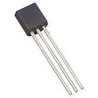
IC LATCH HALL EFFECT 3-SIP
Manufacturer
Allegro Microsystems Inc
Type
Unipolar Switchr
Datasheet
1.A1242ELHLT-I1-T.pdf
(12 pages)
Specifications of A1242LUA-I2-T
Package / Case
3-SIP
Sensing Range
80G Trip, -80G Release
Voltage - Supply
3.5 V ~ 24 V
Current - Supply
6.9mA
Output Type
Digital, Open Drain
Features
Regulated Voltage
Operating Temperature
-40°C ~ 150°C
Peak Reflow Compatible (260 C)
Yes
Termination Type
Through Hole
Supply Voltage Max
24V
No. Of Pins
3
Hall Effect Type
Latching
Supply Voltage Min
3.5V
Lead Free Status / RoHS Status
Lead free / RoHS Compliant
Current - Output (max)
-
Lead Free Status / RoHS Status
Lead free / RoHS Compliant, Lead free / RoHS Compliant


A1242
Operation
The output, I
when a magnetic field perpendicular to the Hall element exceeds
the operate point threshold, B
that is, a south pole of sufficient strength towards the branded
surface of the device switches the device output to I
device retains its output state if the south pole is removed. When
the magnetic field is reduced to below the release point thresh-
old, B
ference between the magnetic operate and release points is called
the hysteresis of the device, B
clean switching of the output even in the presence of external
mechanical vibration and electrical noise.
.
Typical Application Circuit
The A1242 should be protected by an external bypass capaci-
tor, C
GND, of the device. C
noise generated by the chopper-stabilization function. As shown
in figure 2, a 0.01 μF capacitor is typical.
Installation of C
the A1242 pins are no greater than 5 mm in length.
All high-frequency interferences conducted along the supply
lines are passed directly to the load through C
only to protect the A1242 internal circuitry. As a result, the load
ECU (electronic control unit) must have sufficient protection,
other than C
A series resistor on the supply side, R
tion with C
When determining the minimum V
device, the voltage drops across R
R
R
SENSE
SENSE
BYP
RP
, must be taken into consideration. The typical value for
is approximately 100 Ω.
, the device output goes to the low current state. The dif-
, connected between the supply, V
BYP
BYP
CC
, creates a filter for EMI pulses.
, of the A1242 switches to the high current state
, installed in parallel with the A1242.
BYP
must ensure that the traces that connect it to
BYP
reduces both external noise and the
OP
HYS
. Note that the device latches,
. This built-in hysteresis allows
S
CC
and the ECU sense resistor,
S
requirement of the A1242
(not shown), in combina-
Two-Wire Chopper-Stabilized Hall Effect Latch
CC
, and the ground,
BYP
, and it serves
Functional Description
CC(H)
. The
Extensive applications information on magnets and Hall-effect
devices is available in:
• Hall-Effect IC Applications Guide, AN27701,
• Guidelines for Designing Subassemblies
Using Hall-Effect Devices, AN27703.1
• Soldering Methods for Allegro Products – SMD and Through-
All are provided in Allegro Electronic Data Book, AMS-702 and
the Allegro Web site: www.allegromicro.com.
Figure 1. Switching Behavior of the A1242. On the horizontal axis, the
B+ direction indicates increasing south polarity magnetic field strength,
and the B– direction indicates decreasing south polarity field strength
(including the case of increasing north polarity).
Figure 2. Typical Application Circuit
Hole, AN26009
I+
0
V+
B–
A
GND
115 Northeast Cutoff
1.508.853.5000; www.allegromicro.com
Allegro MicroSystems, Inc.
Worcester, Massachusetts 01615-0036 U.S.A.
A1242
ECU
VCC
B
R
HYS
GND
SENSE
0
A
B
Package UA Only
Maximum separation 5 mm
B
B
B+
C
0.01 uF
I
I
BYP
CC(H)
CC(L)
7
Related parts for A1242LUA-I2-T
Image
Part Number
Description
Manufacturer
Datasheet
Request
R

Part Number:
Description:
IC LATCH HALL EFFECT 3-SIP
Manufacturer:
Allegro Microsystems Inc
Datasheet:

Part Number:
Description:
Two-Wire Chopper-Stabilized Hall Effect Latch
Manufacturer:
ALLEGRO [Allegro MicroSystems]
Datasheet:

Part Number:
Description:
CONN DIN PLUG 64POS VERT PCB
Manufacturer:
Tyco Electronics
Datasheet:

Part Number:
Description:
IC, HALL EFFECT SENSOR, Linear, SOIC-8
Manufacturer:
Allegro Microsystems Inc
Datasheet:
Part Number:
Description:
IC, HALL EFFECT SENSOR, Linear, SOIC-8
Manufacturer:
Allegro Microsystems Inc
Datasheet:
Part Number:
Description:
IC, HALL EFFECT SENSOR, Linear, SOIC-8
Manufacturer:
Allegro Microsystems Inc
Datasheet:

Part Number:
Description:
IC SWITCH INTERFACE 2CHAN 8-SOIC
Manufacturer:
Allegro Microsystems Inc
Datasheet:

Part Number:
Description:
IC SMOKE DETECTOR ION 16-DIP
Manufacturer:
Allegro Microsystems Inc
Datasheet:
Part Number:
Description:
IC SMOKE DETECTOR ION 16-DIP
Manufacturer:
Allegro Microsystems Inc
Datasheet:
Part Number:
Description:
IC SMOKE DETECTOR ION 16-DIP
Manufacturer:
Allegro Microsystems Inc
Datasheet:
Part Number:
Description:
IC SMOKE DETECTOR PHOTO 16-DIP
Manufacturer:
Allegro Microsystems Inc
Datasheet:
Part Number:
Description:
IC SMOKE DETECTOR ION 16-DIP
Manufacturer:
Allegro Microsystems Inc
Datasheet:
Part Number:
Description:
IC SMOKE DETECTOR PHOTO 16-DIP
Manufacturer:
Allegro Microsystems Inc
Datasheet:
Part Number:
Description:
IC SMOKE DETECTOR PHOTO 16-DIP
Manufacturer:
Allegro Microsystems Inc
Datasheet:
Part Number:
Description:
IC SMOKE DETECTOR ION 16-DIP
Manufacturer:
Allegro Microsystems Inc
Datasheet: