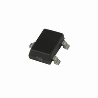
A3230LLHLT Allegro Microsystems Inc, A3230LLHLT Datasheet - Page 9

A3230LLHLT
Manufacturer Part Number
A3230LLHLT
Description
IC SWITCH HALL EFFECT SOT23W
Manufacturer
Allegro Microsystems Inc
Type
Bipolar Latchr
Datasheet
1.A3230EUA.pdf
(13 pages)
Specifications of A3230LLHLT
Sensing Range
25G Trip, -25G Release
Voltage - Supply
3.6 V ~ 24 V
Current - Supply
3.5mA
Current - Output (max)
60mA
Output Type
Digital, Open Drain
Features
Regulated Voltage
Operating Temperature
-40°C ~ 150°C
Package / Case
SOT-23W
Magnetic Type
Bipolar
Operating Supply Voltage (min)
3.6V
Operating Supply Voltage (typ)
5/9/12/15/18V
Operating Supply Voltage (max)
24V
Mag Sensor Operate Point (g)
25Gs
Mag Sensor Release Point (g)
-25Gs
Mag Sensor Hysteresis(g)
15Gs
Package Type
SOT-23W
Pin Count
3
Mounting
Surface Mount
Operating Temp Range
-40C to 150C
Operating Temperature Classification
Automotive
Lead Free Status / RoHS Status
Contains lead / RoHS non-compliant
Available stocks
Company
Part Number
Manufacturer
Quantity
Price
A3230
exhibiting negative switch behavior operate in a similar but
opposite manner. A north polarity fi eld of suffi cient strength,
> B
the result is that V
the fi eld is reduced beyond the B
back to the low state.
The A3230 is designed to attain a small hysteresis, and thereby
provide more sensitive switching. Although this means that
true latching behavior cannot be guaranteed in all cases, proper
switching can be ensured by use of both south and north mag-
netic fi elds, as in a ring magnet.
Bipolar devices adopt an indeterminate output state when
powered-on in the absence of a magnetic fi eld or in a fi eld that
lies within the hysteresis band of the device. The correct state is
attained after the fi rst excursion beyond B
For more information on Bipolar switches, refer to Application
Note 27705, Understanding Bipolar Hall Effect Sensor ICs.
RP
, (more north than B
OUT
switches high, as shown in panel C. When
RP
) is required for operation, although
OP
level, the device switches
Chopper-Stabilized Hall Effect Bipolar Switch
OP
or B
RP
.
Applications
It is strongly recommended that an external bypass capacitor be
connected (in close proximity to the Hall element) between the
supply and ground of the device to reduce both external noise
and noise generated by the chopper stabilization technique. As is
shown in Panel B of fi gure 1, a 0.1μF capacitor is typical.
Extensive applications information on magnets and Hall-effect
devices is available in:
• Hall-Effect IC Applications Guide, AN27701,
• Hall-Effect Devices: Gluing, Potting, Encapsulating, Lead
• Soldering Methods for Allegro’s Products – SMT and Through-
All are provided in Allegro Electronic Data Book, AMS-702 and
the Allegro Web site: www.allegromicro.com
Welding and Lead Forming, AN27703.1
Hole, AN26009
115 Northeast Cutoff
1.508.853.5000; www.allegromicro.com
Allegro MicroSystems, Inc.
Worcester, Massachusetts 01615-0036 U.S.A.
8


