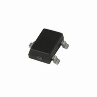
A3240LLHLT Allegro Microsystems Inc, A3240LLHLT Datasheet - Page 5

A3240LLHLT
Manufacturer Part Number
A3240LLHLT
Description
IC SWITCH HALL EFFECT SOT23W
Manufacturer
Allegro Microsystems Inc
Type
Special Purposer
Specifications of A3240LLHLT
Sensing Range
50G Trip, 5G Release
Voltage - Supply
4.2 V ~ 24 V
Current - Supply
6mA
Current - Output (max)
25mA
Output Type
Digital, Open Collector
Features
Regulated Voltage
Operating Temperature
-40°C ~ 150°C
Package / Case
SOT-23W
Magnetic Type
Bipolar
Operating Supply Voltage (min)
4.2V
Operating Supply Voltage (typ)
5/9/12/15/18V
Operating Supply Voltage (max)
24V
Output Current
25mA
Mag Sensor Operate Point (g)
50Gs
Mag Sensor Release Point (g)
5Gs
Mag Sensor Hysteresis(g)
10Gs
Package Type
SOT-23W
Pin Count
3
Mounting
Surface Mount
Operating Temp Range
-40C to 150C
Operating Temperature Classification
Automotive
Lead Free Status / RoHS Status
Contains lead / RoHS non-compliant
Available stocks
Company
Part Number
Manufacturer
Quantity
Price
Part Number:
A3240LLHLT-T
Manufacturer:
ALLEGRO/雅丽高
Quantity:
20 000
A3240
ELECTRICAL CHARACTERISTICS over operating temperature range.
NOTES: 1. Maximum voltage must be adjusted for power dissipation and junction temperature.
MAGNETIC CHARACTERISTICS over operating supply voltage and temperature ranges.
NOTES: 1. Typical Data is at T
Characteristic
Supply Voltage Range
Output Leakage Current
Output Saturation Voltage
Output Current Limit
Power-On Time
Chopping Frequency
Output Rise Time
Output Fall Time
Supply Current
Reverse Battery Current
Zener Voltage
Zener Impedance
Characteristic
Operate Point
Release Point
Hysteresis
2. B
3. Typical Data is at T
2. 1 gauss (G) is exactly equal to 0.1 millitesla (mT).
OP
= operate point (output turns on); B
A
A
= +25°C and V
= +25°C and V
Chopper-Stabilized, Precision Hall-Effect Switch
V
Symbol
Symbol
V
z
OUT(SAT)
z
Z
V
I
B
B
B
I
I
I
OFF
t
OM
f
CC
CC
+ z
CC
po
t
t
CC
+ V
hys
CC
C
OP
RP
r
f
= 12 V and is for design information only.
D
= 12 V and is for design information only.
RP
D
= release point (output turns off).
Test Conditions
Operating, T
V
I
B > B
V
R
R
B < B
B > B
V
I
I
Test Conditions
B
OUT
CC
CC
OUT
CC
RCC
L
L
OP
= 820 , C
= 820 , C
= 15 mA, T
= 15 mA, T
> 4.2 V
= 20 mA, B > B
- B
= 24 V, B < B
OP
RP
OP
= -30 V
, V
RP
, V
CC
CC
J
= 12 V
= 12 V
< 170°C
L
L
A
A
= 20 pF
= 20 pF
= 25°C
= 25°C
RP
OP
1
115 Northeast Cutoff
1.508.853.5000; www.allegromicro.com
Allegro MicroSystems, Inc.
Worcester, Massachusetts 01615-0036 U.S.A.
Min.
Min.
4.2
5.0
30
28
–
–
–
–
–
–
–
–
–
–
–
–
Typ.
Typ.
185
340
0.2
0.1
3.0
4.0
32
50
35
25
10
–
–
–
–
–
Limits
Limits
Max.
Max.
-5.0
500
2.0
2.0
6.0
6.0
24
10
60
50
37
50
–
–
–
–
Units
Units
kHz
mV
mA
mA
mA
mA
μA
μs
μs
μs
V
V
G
G
G
4


