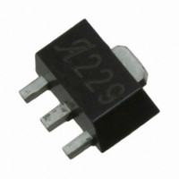
A3251LLT Allegro Microsystems Inc, A3251LLT Datasheet - Page 4

A3251LLT
Manufacturer Part Number
A3251LLT
Description
IC SW HALL EFFECT UNI SOT-89
Manufacturer
Allegro Microsystems Inc
Type
Unipolar Switchr
Datasheet
1.A3251EUA-T.pdf
(16 pages)
Specifications of A3251LLT
Sensing Range
50G
Voltage - Supply
4.2 V ~ 24 V
Current - Supply
10mA
Current - Output (max)
20mA
Output Type
Digital, Open Collector
Features
Regulated Voltage
Operating Temperature
-40°C ~ 150°C
Package / Case
SOT-89-3
Lead Free Status / RoHS Status
Contains lead / RoHS non-compliant
A3250
A3251
1
2
3
switchpoint has been achieved.
OPERATING CHARACTERISTICS valid over operating T
ELECTRICAL CHARACTERISTICS
Supply Voltage
Output Saturation Voltage
Output Leakage Current
Supply Current
Output Rise Time
Output Fall Time
Chopping Frequency
Power-Up Time
Output Current Limit
Power-On State
MAGNETIC CHARACTERISTICS
Initial Operate Point
Temperature Drift of B
Hysteresis (B
PROGRAMMING CHARACTERISTICS
Programmable B
Number of Programming Bits
Resolution
TRANSIENT PROTECTION CHARACTERISTICS
Supply Zener Voltage
Supply Zener Current
Reverse Battery Current
Do not exceed T
Short-circuit protection is not intended for continuous operation; permanent damage may result.
Device can be used below 50 G but is not guaranteed to be a unipolar switch. It is the responsibility of the programmer to verify that the desired
Characteristic
OP
and
1
J
(max): Additional information on power derating is provided in the applications section.
– B
OP
RP
Values
1,2
OP
)
3
V
B
Symbol
I
I
OUT(lim)
I
OUT(sat)
ΔB
OP(prog)
B
CC(off)
CC(on)
POS
I
I
B
V
B
OFF
RCC
t
V
f
RES
I
on
–
CC
t
t
hys
OP
C
Z
r
f
OP
Z
Running mode
I
V
A3250; B < B
A3251; B > B
A3250; B > B
A3251; B < B
R
R
V
Short-circuit protection
A3250; B < B
A3251; B < B
B
Package T
Package T
Switchpoint set
Programming lock
V
V
OUT
Field-Programmable, Chopper-Stabilized,
OUT
OUT
OP
CC
RCC
LOAD
LOAD
≤ 500 gauss
= 28 V
= 20 mA; Switch state = ON
= 24 V; Switch state = OFF
= HIGH
= –18 V, T
= 820 Ω, C
= 820 Ω, C
A
A
A
and V
range = J
range = L
RP
OP
OP
RP
RP
RP
Test Conditions
; V
; V
; V
; V
, t > t
, t > t
J
CC
< T
OUT
OUT
LOAD
LOAD
OUT
OUT
, unless otherwise specified
on
on
J(max)
= HIGH
= LOW
= HIGH
= LOW
= 10 pF
= 10 pF
Unipolar Hall-Effect Switches
115 Northeast Cutoff, Box 15036
Min.
Allegro MicroSystems, Inc.
Worcester, Massachusetts 01615-0036 (508) 853-5000
www.allegromicro.com
–35
–20
4.2
5.0
5.0
60
50
28
–
–
–
–
–
–
–
–
–
–
–
–
–
–
–
–
–
HIGH
LOW
Typ.
175
340
4.0
4.0
6.0
6.0
7.0
20
90
13
18
13
–
–
–
–
–
–
6
1
–
–
–
Max.
≥350
10.0
10.0
–5.0
400
120
7.0
7.0
5.0
5.0
24
10
50
50
35
35
35
13
–
–
–
–
–
–
–
Units
kHz
mV
mV
mV
mA
mA
mA
mA
mA
mA
mA
μA
Bit
Bit
μs
μs
μs
G
G
G
G
G
G
V
V
3


