ATS643LSH-I1TN Allegro Microsystems Inc, ATS643LSH-I1TN Datasheet - Page 4
ATS643LSH-I1TN
Manufacturer Part Number
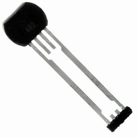
ATS643LSH-I1TN
Description
IC SENSOR GEAR TOOTH 4-SIP
Manufacturer
Allegro Microsystems Inc
Type
Special Purposer
Datasheet
1.ATS643LSH-I1TN.pdf
(15 pages)
Specifications of ATS643LSH-I1TN
Sensing Range
65% Trip, 35% Release
Voltage - Supply
4 V ~ 24 V
Current - Supply
8mA
Output Type
Digital, Open Collector
Features
Gear Tooth Type
Operating Temperature
-40°C ~ 150°C
Package / Case
4-SIP
Lead Free Status / RoHS Status
Contains lead / RoHS non-compliant
Current - Output (max)
-


ATS643LSH
OPERATING CHARACTERISTICS (continued) using reference target 60-0, T
SWITCHPOINT CHARACTERISTICS
Rotation Speed
Bandwidth
Operate Point
Release Point
CALIBRATION
Initial Calibration Period
AGC Calibration Disable
Start Mode Hysteresis
DAC CHARACTERISTICS
Dynamic Offset Cancellation
Tracking Data Resolution
FUNCTIONAL CHARACTERISTICS
Air Gap Range
Maximum Operable Air Gap
Duty Cycle Variation
Input Signal Range
Minimum Operable Input Signal
1
2
of the bypass capacitor, if one is used.
3
4
characterized. The field available from the reference target is given in the reference target parameter section of the datasheet.
Power-On Time includes the time required to complete the internal automatic offset adjust. The DACs are then ready for peak acquisition.
dI is the difference between 10% of I
Continuous Update (calibration) functions continuously during Running mode operation.
AG is dependent on the available magnetic field. The available field is dependent on target geometry and material, and should be independently
Characteristic
4
3
CC(Low)
AG
Sig
Symbol
PO
S
∆DC
B
BW
B
AG
Sig
(opmax)
(opmin)
C
C
ROT
and 90% of I
OP
RP
Gear Tooth Sensor IC with Continuous Update
HYS
I
f
Reference Target 60-0
Equivalent to f – 3dB
Quantity of rising output (current) edges required for
accurate edge detection
Quantity of rising output (current) edges used for
calibrating AGC
Quantity of bits available for PDAC/NDAC tracking of
both positive and negative signal peaks
∆DC within specification
Output switching (no missed edges); ∆DC not
guaranteed
Wobble < 0.5 mm, AG within specification
∆DC within specification
Output switching (no missed edges); ∆DC not
guaranteed
% of peak to peak referenced from PDAC to NDAC,
AG < AG
% of peak to peak referenced from PDAC to NDAC,
AG < AG
CC(High)
Self-Calibrating, Zero-Speed Differential
, and dt is time period between those two points. Note: dI/dt is dependent upon the value
MAX
MAX
Test Conditions
A
and V
CC
within specification, unless otherwise noted
115 Northeast Cutoff
1.508.853.5000; www.allegromicro.com
Allegro MicroSystems, Inc.
Worcester, Massachusetts 01615-0036 U.S.A.
Min.
0.5
25
40
30
0
–
–
–
–
–
–
–
–
–
Typ.
175
±60
40
65
35
–
–
–
–
–
–
9
–
–
12,000
Max.
1400
2.75
±10
2.5
–
–
–
3
3
–
–
–
–
Units
Edge
Edge
rpm
kHz
mm
mm
mV
Bit
%
%
%
G
G
G
4
Related parts for ATS643LSH-I1TN
Image
Part Number
Description
Manufacturer
Datasheet
Request
R

Part Number:
Description:
IC SENSOR GEAR TOOTH 4-SIP
Manufacturer:
Allegro Microsystems Inc
Datasheet:

Part Number:
Description:
Ats643lsh Self-calibrating Zero-speed Differential Gear Tooth Sensors With Continuous Update
Manufacturer:
Allegro MicroSystems, Inc.
Datasheet:

Part Number:
Description:
IC, HALL EFFECT SENSOR, Linear, SOIC-8
Manufacturer:
Allegro Microsystems Inc
Datasheet:
Part Number:
Description:
IC, HALL EFFECT SENSOR, Linear, SOIC-8
Manufacturer:
Allegro Microsystems Inc
Datasheet:
Part Number:
Description:
IC, HALL EFFECT SENSOR, Linear, SOIC-8
Manufacturer:
Allegro Microsystems Inc
Datasheet:

Part Number:
Description:
IC SWITCH INTERFACE 2CHAN 8-SOIC
Manufacturer:
Allegro Microsystems Inc
Datasheet:

Part Number:
Description:
IC SMOKE DETECTOR ION 16-DIP
Manufacturer:
Allegro Microsystems Inc
Datasheet:
Part Number:
Description:
IC SMOKE DETECTOR ION 16-DIP
Manufacturer:
Allegro Microsystems Inc
Datasheet:
Part Number:
Description:
IC SMOKE DETECTOR ION 16-DIP
Manufacturer:
Allegro Microsystems Inc
Datasheet:
Part Number:
Description:
IC SMOKE DETECTOR PHOTO 16-DIP
Manufacturer:
Allegro Microsystems Inc
Datasheet:
Part Number:
Description:
IC SMOKE DETECTOR ION 16-DIP
Manufacturer:
Allegro Microsystems Inc
Datasheet:
Part Number:
Description:
IC SMOKE DETECTOR PHOTO 16-DIP
Manufacturer:
Allegro Microsystems Inc
Datasheet:
Part Number:
Description:
IC SMOKE DETECTOR PHOTO 16-DIP
Manufacturer:
Allegro Microsystems Inc
Datasheet:
Part Number:
Description:
IC SMOKE DETECTOR ION 16-DIP
Manufacturer:
Allegro Microsystems Inc
Datasheet:
Part Number:
Description:
IC SMOKE DETECTOR PHOTO 16-SOIC
Manufacturer:
Allegro Microsystems Inc
Datasheet: