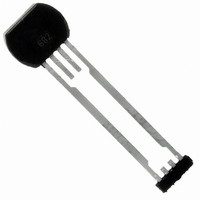
ATS645LSH-I2TN Allegro Microsystems Inc, ATS645LSH-I2TN Datasheet

ATS645LSH-I2TN
Specifications of ATS645LSH-I2TN
Related parts for ATS645LSH-I2TN
ATS645LSH-I2TN Summary of contents
Page 1
... However, Allegro MicroSystems, Inc. assumes no respon- sibility for its use; nor for any infringements of patents or other rights of third parties which may result from its use. Peak-Detecting Gear Tooth Sensor IC Not for New Design ATS645LSH ...
Page 2
... Hall-effect integrated circuit that has been optimized to the magnetic circuit. This small package can be easily assembled and used in conjunction with a wide variety of gear shapes and sizes. Continued on the next page… Functional Block Diagram Gain AGC DAC Internal Regulator Test Signals ATS645LSH VCC GND Test ...
Page 3
... Wide operating voltage range • Defined power-on state Part Number ATS645LSHTN-I1-T Tape and Reel 13-in. 800 pcs./reel ATS645LSHTN-I2-T Tape and Reel 13-in. 800 pcs./reel * Contact Allegro for additional packing options. Some restrictions may apply to certain types of sales. Contact Allegro for details. ...
Page 4
... V 0 → and 5 → mA 25° CC(max) A Test conditions only ATS645LSH-I1 ATS645LSH-I2 ATS645LSH-I1 ATS645LSH-I2 / Ratio of high current to low current t > Target gear speed < 100 rpm R = 100 Ω LOAD LOAD within specifi cation, unless otherwise noted 1 Min. Typ. 4.0 – – ...
Page 5
... ATS645LSH OPERATING CHARACTERISTICS (continued) using reference target 60-0, T Characteristic SWITCHPOINT CHARACTERISTICS Rotation Speed Analog Signal Bandwidth Operate Point Release Point CALIBRATION Initial Calibration DAC CHARACTERISTICS Allowable User-Induced Differential Offset 5 FUNCTIONAL CHARACTERISTICS Operational Air Gap Range 6 Maximum Operational Air Gap AG Range 7 Duty Cycle Variation ...
Page 6
... ATS645LSH REFERENCE TARGET, 60-0 (60 Tooth Target) Characteristics Symbol Outside Diameter D o Face Width F Circular Tooth Length t Circular Valley Length t v Tooth Whole Depth h t Material Reference Gear Magnetic Gradient Amplitude With Reference to Air Gap 800 700 600 500 400 300 200 ...
Page 7
... ATS645LSH Duty Cycle vs. Air Gap 100 RPM 0.5 1 1.5 Air Gap (mm) Duty Cycle vs. Air Gap 1000 RPM 0.5 1 1.5 Air Gap (mm) True Zero Speed Miniature Differential Peak- Detecting Gear Tooth Sensor IC Characteristic Data I1 Trim (º -40 25 150 2 (ºC) A -40 ...
Page 8
... ATS645LSH THERMAL CHARACTERISTICS may require derating at maximum conditions, see application information CHARACTERISTIC Package Thermal Resistance *Additional information is available on the Allegro Web site. True Zero Speed Miniature Differential Peak- Detecting Gear Tooth Sensor IC Symbol TEST CONDITIONS* Single-layer PCB with copper limited to solder pads R Two-layer PCB with 3 ...
Page 9
... ATS645LSH Hall Technology The gear tooth sensor IC subassembly contains a single-chip differential Hall effect sensor IC, an optimized samarium cobalt pellet, and a fl at ferrous pole piece. The Hall IC supports two Hall elements, which sense the magnetic profi the ferromag- netic target simultaneously, but at different points (spaced ...
Page 10
... ATS645LSH Automatic Gain Control (AGC) This feature allows the device to operate with an optimal internal electrical signal, regardless of the air gap (within the AG speci- fi cation). During calibration, the device determines the peak-to- peak amplitude of the signal generated by the target. The gain of the IC is then automatically adjusted ...
Page 11
... ATS645LSH Power Supply Protection The device contains an on-chip regulator and can operate over a wide V range. For devices that need to operate from an CC unregulated power supply, transient protection must be added externally. For applications using a regulated line, EMI/RFI pro- tection may still be required. Contact Allegro MicroSystems for information on the circuitry needed for compliance with various EMC specifi ...
Page 12
... ATS645LSH DEVICE OPERATION Each operating mode is described in detail below. Power-On When power (V > applied to the device, a short CC CCMIN period of time is required to power the various portions of the IC. During this period, the ATS645 is guaranteed to power-on in the high current state CC(High) Initial Offset Adjust The IC intially cancels the effects of chip, magnet, and installa- tion offsets ...
Page 13
... ATS645LSH The device must be operated below the maximum junction temperature of the device Under certain combinations of J(max) peak conditions, reliable operation may require derating sup- plied power or improving the heat dissipation properties of the application. This section presents a procedure for correlating factors affecting operating T ...
Page 14
... ATS645LSH F 0.75 8.00±0.05 5.80±0.05 E1 1.70±0.10 4.00±0.10 5.00±0. 24.65±0.10 13.10±0.10 A Copyright ©2004-2009, Allegro MicroSystems, Inc. The products described herein are manufactured under one or more of the following U.S. patents: 5,264,783; 5,389,889; 5,442,283; 5,517,112; 5,581,179; 5,619,137; 5,621,319; 5,650,719; 5,686,894; 5,694,038; 5,729,130; 5,917,320; 6,091,239; 6,100,680; 6,232,768; 6,242,908; 6,265,865; ...


