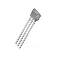
A3211EUA-T Allegro Microsystems Inc, A3211EUA-T Datasheet - Page 8

A3211EUA-T
Manufacturer Part Number
A3211EUA-T
Description
IC SWITCH HALL EFFECT 3-SIP
Manufacturer
Allegro Microsystems Inc
Type
Digital Omnipolar Switchr
Datasheet
1.A3212ELHLT-T.pdf
(12 pages)
Specifications of A3211EUA-T
Sensing Range
±55G Trip, ±10G Release
Voltage - Supply
2.5 V ~ 3.5 V
Current - Supply
2mA
Current - Output (max)
1mA
Output Type
Digital, Open Collector
Features
Ultra Sensitive
Operating Temperature
-40°C ~ 85°C
Package / Case
3-SIP
Magnetic Type
Latch
Operating Supply Voltage (min)
2.5V
Operating Supply Voltage (typ)
2.75V
Operating Supply Voltage (max)
3.5V
Output Current
1mA
Mag Sensor Operate Point (g)
55Gs
Mag Sensor Release Point (g)
10Gs
Mag Sensor Hysteresis(g)
5.9Gs
Package Type
Ultra Mini SIP
Pin Count
3
Mounting
Through Hole
Operating Temp Range
-40C to 85C
Operating Temperature Classification
Industrial
Lead Free Status / RoHS Status
Lead free / RoHS Compliant
A3211
A3212
Operation. The output of the A3212 switches low (turns on)
when a magnetic field perpendicular to the Hall element exceeds
the operate point B
output is capable of sinking up to 1 mA and the output voltage
is V
release point B
switches high (turns off). The dif fer ence in the magnetic operate
and release points is the hysteresis (B
built-in hysteresis allows clean switching of the output even
in the presence of external mechanical vibration and electrical
noise. The A3211 functions in the same manner, except the out-
put voltage is reversed from the A3212, as shown in the figures
to the right.
As used here, negative flux densities are defined as less than
zero (algebraic convention), i.e., -50 G is less than +10 G.
Applications. Allegro's pole-independent processing tech-
nique allows for operation with either a north pole or south
pole magnet orientation, enhancing the manufacturability of the
device. The state-of-the-art technology provides the same output
polarity for either pole face.
be con nect ed (in close proximity to the Hall element) between
the supply and ground of the device to reduce both external
noise and noise generated by the chopper-sta bi li za tion tech nique.
This is especially true due to the relatively high im ped ance of
battery supplies.
is a bar magnet with either pole near the branded surface of the
device. Many oth er meth ods of operation are possible. Ex ten-
sive applications information for Hall-effect devices is available
in:
• Hall-Effect IC Applications Guide, Application Note 27701;
• Hall-Effect Devices: Soldering, Gluing, Potting, En cap su lat-
ing, and Lead Forming, Application Note 27703.1;
• Soldering of Through-Hole Hall-Sensing Dervices, Application
Note 27703; and
• Soldering of Surface-Mount Hall-Sensing Devices, Application
Note 27703.2.
All are provided at
OUT(ON)
It is strongly recommended that an external bypass ca pac i tor
The sim plest form of magnet that will op er ate these devices
and
. When the magnetic field is reduced below the
RPS
www.allegromicro.com
(or increased above B
OPS
(or is less than B
hys
OPN
) of the device. This
RPN
FUNCTIONAL DESCRIPTION (cont'd)
). After turn-on, the
), the device output
MAX
MAX
5 V
5 V
Micropower, Ultrasensitive
0
0
-B
-B
A3212
A3211
OUTPUT OFF
OUTPUT ON
X
B OPN
B OPN
Hall-Effect Switches
115 Northeast Cutoff
1.508.853.5000; www.allegromicro.com
Allegro MicroSystems, Inc.
Worcester, Massachusetts 01615-0036 U.S.A.
B
B RPN
RPN
MAGNETIC FLUX
MAGNETIC FLUX
OUTPUT OFF
OUTPUT ON
0
0
B RPS
B
RPS
0.1 ∝F
B
B OPS
OPS
OUTPUT ON
OUTPUT OFF
OUT P UT
S UP P LY
(3 V B ATTE R Y )
Dwg. E H-013-2
+B
+B
8


