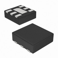
ISL29013IROZ-T7 Intersil, ISL29013IROZ-T7 Datasheet - Page 8

ISL29013IROZ-T7
Manufacturer Part Number
ISL29013IROZ-T7
Description
IC SENSOR LIGHT-DGTL I2C 6-ODFN
Manufacturer
Intersil
Datasheet
1.ISL29013IROZ-EVALZ.pdf
(15 pages)
Specifications of ISL29013IROZ-T7
Wavelength
540nm
Output Type
I²C™
Package / Case
6-ODFN
Rohs Compliant
Yes
Lead Free Status / RoHS Status
Lead free / RoHS Compliant
Other names
ISL29013IROZ-T7TR
Available stocks
Company
Part Number
Manufacturer
Quantity
Price
Company:
Part Number:
ISL29013IROZ-T7
Manufacturer:
Intersil
Quantity:
25
INTEGRATION TIME IN INTERNAL TIMING MODE
This timing mode is programmed in the command register
00(hex) Bit 5. Most applications will be using this timing
mode. When using the Internal Timing Mode, f
n-bits resolution determine the integration time. t
function of the number of clock cycles and f
Equation 9:
t
Since f
t
is shown in Equation 10:
t
INTEGRATION TIME IN EXTERNAL TIMING MODE
This timing mode is programmed in the command register
00(hex) Bit 5. External Timing Mode is recommended when
integration time can be synchronized to an external signal
such as a PWM to eliminate noise.
To read the light count DATA output, the device needs three
sync_I
sync_I
The 2nd sync_I
and starts the conversion of diode array 2. The 3rd sync_I
pules ends the conversion of diode array 2, outputs the light
t
TABLE 13. INTEGRATION TIMES FOR TYPICAL REXT VALUES
*Integration time in milliseconds
**Recommended
INT
INT
INT
INT
m = 4, 8, 12, and16. n is the number of bits of resolution.
2
programmed at the command register 00(hex) Bits 1 and 0.
t
for Internal Timing Mode and Gain/Range is set to Range1
or Range2.
t
for Internal Timing Mode and Gain/Range is set to Range3
or Range4.
INT1
INT
R
100**
m
(kΩ)
1
200
500
2
EXT
50
is dual time. The integration time as a function of R
=
therefore is the number of clock cycles. n can be
=
2
=
2
2
2
OSC
C commands to complete one measurement. The 1st
C command starts the conversion of the diode array 1.
m
is the integration time when the device is configured
is the integration time when the device is configured
2
2
m
m
×
×
×
----------
f
is dual speed depending on the Gain/Range bit,
osc
n = 15-BIT
1
--------------------------------------------- -
327kHz
--------------------------------------------- -
655kHz
1000
2
100
200
400
R
C completes the conversion of diode array 1
EXT resistor value
R
R
for Internal Timing Mode only
RANGE1
RANGE2
EXT
EXT
×
×
100kΩ
100kΩ
n = 11-BIT
6.4
13
26
64
8
n = 11-BIT
3.2
6.5
13
32
OSC
RANGE3
RANGE4
OSC
as shown in
INT
and
0.013
0.025
0.050
0.125
is a
n = 3
(EQ. 11)
(EQ. 10)
(EQ. 9)
EXT
2
C
ISL29013
count DATA, and starts over again to commence conversion
of diode array 1.
The integration time, t
intervals between the three sync pulses. t
by Equation 12:
where K
from Timer data register and f
operating frequency
The internal oscillator, f
internal and external timing modes, with the same
dependence on R
the number of clock cycles per integration is no longer fixed
at 2
integration time, and is limited to 2
avoid erroneous lux readings the integration time must be
short enough not to allow an overflow in the counter register.
Noise Rejection
In general, integrating type ADC’s have excellent
noise-rejection characteristics for periodic noise sources
whose frequency is an integer multiple of the integration
time. For instance, a 60Hz AC unwanted signal’s sum from
0ms to k*16.66ms (k = 1,2...k
device’s integration time to be an integer multiple of the
periodic noise signal, greatly improves the light sensor
output signal in the presence of noise.
Maximum Ambient Intensity Condition
The operation of ambient light sensing (ALS) within the
ISL29013 utilizes two diodes, D1 and D2. The diodes are
measured sequentially and their outputs are converted with
an ADC. The output of the ALS is the difference between
these two measurements. In typical applications, the
ISL29013 is installed behind a dark cover window. In this
low-light condition, both D1 and D2 operate linearly and the
ALS output is linear as well (Figures 19 and 20). In brighter
environments, however, D1 and D2 can be subject to
saturation. As the ambient light grows bright enough to
subject one or both diodes to saturation, the ALS count
(output) decreases and eventually reaches zero in deep
saturation (Figure 18). When using the ISL29013 in high lux
applications, be sure to choose a low R
saturation at Range4, the lowest gain. For example,
R
t
t
INT
INT
EXT
f
Range1 or Range2.
f
Range3 or Range4.
OSC
osc
n
<
. The number of clock cycles varies with the chosen
=
65,535
----------------- -
= 25kΩ is recommended with ambient light near
= 655kHz*100kΩ/R
f
k
-------------- -
f
OSC
= 327kHz*100kΩ/R
OSC
OSC
OSC
is the number of internal clock cycles obtained
EXT
. However, in External Timing Mode,
INT
OSC
, is the sum of two identical time
EXT
EXT
, operates identically in both the
i
OSC
. When Range/Gain is set to
) is zero. Similarly, setting the
. When Range/Gain is set to
16
is the internal I
= 65,536. In order to
EXT
INT
to avoid
is determined
September 2, 2008
2
C
(EQ. 12)
(EQ. 13)
FN6485.2


