AD590JF Analog Devices Inc, AD590JF Datasheet - Page 9
AD590JF
Manufacturer Part Number
AD590JF
Description
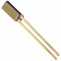
IC TEMP TRANSDUCER 2-TERM 2-CQFP
Manufacturer
Analog Devices Inc
Specifications of AD590JF
Sensing Temperature
-55°C ~ 150°C
Output Type
Current
Voltage - Supply
4 V ~ 30 V
Accuracy
±5°C
Package / Case
2-CQFP
Ic Output Type
Current
Sensing Accuracy Range
± 5°C
Supply Voltage Range
4V To 30V
Sensor Case Style
Flatpack
No. Of Pins
2
Termination Type
SMD
Body Style
Flatpack
Current, Supply
298.2 μA (Typ.) @ 25 °C
Current, Switching
298.2 μA
Function
Temperature
Linearity
± 0.3 °C
Output
Current
Primary Type
Temperature
Range, Measurement
150 °C
Temperature Coefficient
1 μA⁄K (Typ.)
Temperature, Operating, Maximum
150 °C
Temperature, Operating, Minimum
-55 °C
Temperature, Soldering
300 °C
Termination
Solder
Voltage, Forward
44 V
Voltage, Output
4 V (Min.)
Voltage, Reverse
-20 V
Voltage, Supply
30 V
2-terminal Device
voltage in⁄current out
Filter Terminals
SMD
Rohs Compliant
Yes
Lead Free Status / RoHS Status
Lead free / RoHS Compliant
Lead Free Status / RoHS Status
Lead free / RoHS Compliant, Lead free / RoHS Compliant


Table 4. Thermal Resistance
Medium
Aluminum Block
Stirred Oil
Moving Air
Still Air
1
2
3
The time response of the AD590 to a step change in
temperature is determined by the thermal resistances and the
thermal capacities of the chip, C
about 0.04 Ws/°C for the AD590. C
medium, because it includes anything that is in direct thermal
contact with the case. The single time constant exponential
curve of Figure 15 is usually sufficient to describe the time
response, T (t). Table 4 shows the effective time constant, τ, for
several media.
τ is dependent upon velocity of oil; average of several velocities listed above.
Air velocity @ 9 ft/sec.
The time constant is defined as the time required to reach 63.2% of an
instantaneous temperature change.
With Heat Sink
Without Heat Sink
With Heat Sink
Without Heat Sink
2
3
H
30
42
45
115
191
480
(°C/Watt)
θ
JC
CH
+ θ
, and the case, C
C
CA
F
10
60
–
190
–
650
varies with the measured
H
0.6
1.4
5.0
13.5
108
60
C
. C
τ (sec)
CH
is
F
0.1
0.6
–
10.0
–
30
1
Rev. E | Page 9 of 16
T
T
INITIAL
FINAL
τ
Figure 15. Time Response Curve
T(t) = T
INITIAL
+ (T
TIME
FINAL
4τ
– T
INITIAL
)
×
(1 – e
–t/τ
)
AD590
Related parts for AD590JF
Image
Part Number
Description
Manufacturer
Datasheet
Request
R

Part Number:
Description:
±1.7g Dual-Axis IMEMS Accelerometer Evaluation Board
Manufacturer:
Analog Devices Inc
Datasheet:

Part Number:
Description:
Inertial Sensor Evaluation System
Manufacturer:
Analog Devices Inc
Datasheet:
Part Number:
Description:
Manufacturer:
Analog Devices Inc
Datasheet:
Part Number:
Description:
Manufacturer:
Analog Devices Inc
Datasheet:
Part Number:
Description:
Manufacturer:
Analog Devices Inc
Datasheet:
Part Number:
Description:
Manufacturer:
Analog Devices Inc
Datasheet:
Part Number:
Description:
Manufacturer:
Analog Devices Inc
Datasheet:
Part Number:
Description:
Manufacturer:
Analog Devices Inc
Datasheet:
Part Number:
Description:
Manufacturer:
Analog Devices Inc
Datasheet:
Part Number:
Description:
Manufacturer:
Analog Devices Inc
Datasheet:
Part Number:
Description:
Manufacturer:
Analog Devices Inc
Datasheet:
Part Number:
Description:
Manufacturer:
Analog Devices Inc
Datasheet:
Part Number:
Description:
Manufacturer:
Analog Devices Inc
Datasheet: