AD592CN Analog Devices Inc, AD592CN Datasheet - Page 4
AD592CN
Manufacturer Part Number
AD592CN
Description
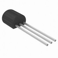
IC TEMP TRANSDUCER 2-TERM TO92-3
Manufacturer
Analog Devices Inc
Datasheet
1.DF36022FPV.pdf
(8 pages)
Specifications of AD592CN
Rohs Status
RoHS non-compliant
Sensing Temperature
-25°C ~ 105°C
Output Type
Current
Voltage - Supply
4 V ~ 30 V
Accuracy
±0.3°C
Package / Case
TO-226-3, TO-92-3 (TO-226AA)
Termination Type
Through Hole
Mounting Type
Through Hole
Operating Temperature Range
-25°C To +105°C
Peak Reflow Compatible (260 C)
No
Ic Function
Temperature Sensor IC
Leaded Process Compatible
No
Temperature Sensor Function
Temp Sensor
Package Type
TO-92
Operating Temperature (min)
-25C
Operating Temperature Classification
Commercial
Operating Supply Voltage (min)
4V
Operating Supply Voltage (typ)
5/9/12/15/18/24V
Operating Supply Voltage (max)
30V
Lead Free Status / Rohs Status
Not Compliant
Available stocks
Company
Part Number
Manufacturer
Quantity
Price

Company:
Part Number:
AD592CN
Manufacturer:
SIEMENS
Quantity:
5 510


AD592
THEORY OF OPERATION
The AD592 uses a fundamental property of silicon transistors
to realize its temperature proportional output. If two identical
transistors are operated at a constant ratio of collector current
densities, r, then the difference in base-emitter voltages will be
(kT/q)(ln r). Since both k, Boltzman’s constant and q, the
charge of an electron are constant, the resulting voltage is
directly Proportional To Absolute Temperature (PTAT). In the
AD592 this difference voltage is converted to a PTAT current
by low temperature coefficient thin film resistors. This PTAT
current is then used to force the total output current to be pro-
portional to degrees Kelvin. The result is a current source with
an output equal to a scale factor times the temperature (K) of
the sensor. A typical V-I plot of the circuit at +25 C and the
temperature extremes is shown in Figure 1.
Factory trimming of the scale factor to 1 A/K is accomplished
at the wafer level by adjusting the AD592’s temperature reading
so it corresponds to the actual temperature. During laser trim-
ming the IC is at a temperature within a few degrees of 25 C
and is powered by a 5 V supply. The device is then packaged
and automatically temperature tested to specification.
FACTORS AFFECTING AD592 SYSTEM PRECISION
The accuracy limits given on the Specifications page for the
AD592 make it easy to apply in a variety of diverse applications.
To calculate a total error budget in a given system it is impor-
tant to correctly interpret the accuracy specifications, non-
linearity errors, the response of the circuit to supply voltage
variations and the effect of the surrounding thermal environ-
ment. As with other electronic designs external component se-
lection will have a major effect on accuracy.
CALIBRATION ERROR, ABSOLUTE ACCURACY AND
NONLINEARITY SPECIFICATIONS
Three primary limits of error are given for the AD592 such that
the correct grade for any given application can easily be chosen
for the overall level of accuracy required. They are the calibra-
tion accuracy at +25 C, and the error over temperature from
0 C to +70 C and –25 C to +105 C. These specifications cor-
respond to the actual error the user would see if the current out-
put of an AD592 were converted to a voltage with a precision
378
298
248
0
Figure 1. V-I Characteristics
1
SUPPLY VOLTAGE – Volts
2
3
4
+105
+25
–25
o
o
o
C
C
UP TO
C
30V
5
6
–4–
resistor. Note that the maximum error at room temperature,
over the commercial IC temperature range, or an extended
range including the boiling point of water, can be directly read
from the specifications table. All three error limits are a combi-
nation of initial error, scale factor variation and nonlinearity de-
viation from the ideal 1 A/K output. Figure 2 graphically
depicts the guaranteed limits of accuracy for an AD592CN.
The AD592 has a highly linear output in comparison to older
technology sensors (i.e., thermistors, RTDs and thermo-
couples), thus a nonlinearity error specification is separated
from the absolute accuracy given over temperature. As a maxi-
mum deviation from a best-fit straight line this specification rep-
resents the only error which cannot be trimmed out. Figure 3 is
a plot of typical AD592CN nonlinearity over the full rated tem-
perature range.
TRIMMING FOR HIGHER ACCURACY
Calibration error at 25 C can be removed with a single tempera-
ture trim. Figure 4 shows how to adjust the AD592’s scale fac-
tor in the basic voltage output circuit.
+1.0
+0.5
–0.5
–1.0
Figure 2. Error Specifications (AD592CN)
+0.2
+0.1
–0.1
–0.2
Figure 3. Nonlinearity Error (AD592CN)
0
–25
0
–25
0
0
TEMPERATURE –
TEMPERATURE –
+25
+25
TYPICAL ERROR
MAXIMUM ERROR
OVER TEMPERATURE
CALIBRATION
ERROR LIMIT
TYPICAL NONLINEARITY
MAXIMUM ERROR
OVER TEMPERATURE
o
o
C
C
+70
+70
+105
+105
REV. A
Related parts for AD592CN
Image
Part Number
Description
Manufacturer
Datasheet
Request
R

Part Number:
Description:
±1.7g Dual-Axis IMEMS Accelerometer Evaluation Board
Manufacturer:
Analog Devices Inc
Datasheet:

Part Number:
Description:
Inertial Sensor Evaluation System
Manufacturer:
Analog Devices Inc
Datasheet:
Part Number:
Description:
Manufacturer:
Analog Devices Inc
Datasheet:
Part Number:
Description:
Manufacturer:
Analog Devices Inc
Datasheet:
Part Number:
Description:
Manufacturer:
Analog Devices Inc
Datasheet:
Part Number:
Description:
Manufacturer:
Analog Devices Inc
Datasheet:
Part Number:
Description:
Manufacturer:
Analog Devices Inc
Datasheet:
Part Number:
Description:
Manufacturer:
Analog Devices Inc
Datasheet:
Part Number:
Description:
Manufacturer:
Analog Devices Inc
Datasheet:
Part Number:
Description:
Manufacturer:
Analog Devices Inc
Datasheet:
Part Number:
Description:
Manufacturer:
Analog Devices Inc
Datasheet:
Part Number:
Description:
Manufacturer:
Analog Devices Inc
Datasheet:
Part Number:
Description:
Manufacturer:
Analog Devices Inc
Datasheet: