AS6H-2KT2PB IDEC, AS6H-2KT2PB Datasheet - Page 16
AS6H-2KT2PB
Manufacturer Part Number
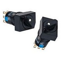
AS6H-2KT2PB
Description
SWITCH, KEY OPERATED, DPDT, 3A, 250V
Manufacturer
IDEC
Datasheet
1.AS6-SK.pdf
(20 pages)
Specifications of AS6H-2KT2PB
Contact Configuration
DPDT
Switch Operation
ON-OFF
Angle Of Throw
90°
Actuator Style
Flat
No. Of Switch Positions
2
Contact Voltage Ac Nom
220V
Contact Voltage Dc Nom
24V
Lead Free Status / RoHS Status
Lead free / RoHS Compliant


• Turn off the power to A series control units before starting
• To avoid a burn on your hand, use the lamp holder tool when
Replacement of Lens and Marking Plate
• Removal
Remove the lens assembly (color lens, marking plate, lens holder,
and spring) by holding the color lens recesses with the Lens
Removal Tool (MT-101) and pulling it out. Remove the marking plate
by disengaging the latches between the color lens and lens holder.
The marking plate must be
engraved on the front side
as shown at right.
When using a color film,
insert it between the color
lens and marking plate.
• Installation
Place the marking plate on
the lens holder in the correct direction, and press the color lens onto
the lens holder to engage the latches.
Put the spring on the lens holder and insert the lens holder into the
housing in the correct direction.
Marking
For A series illuminated pushbuttons, legends and symbols can be
engraved on the built-in marking plates, or printed film can be
inserted under the lens for labelling purposes.
Marking Plate & Engraving Area
Replacing the LED Lamp
• Removal
Use the lamp holder tool (OR-77) to remove lamps. Do not use
pliers.
• Installation
Use the lamp holder tool (OR-77) to install lamps. Note the correct
side of the tool for removal or installation.
(06/11/10)
Built-in Marking
Engraving Area
installation, removal, wiring, maintenance, and inspection of the
control units. Failure to turn power off may cause electrical shocks
or fire hazard.
replacing lamps.
(not supplied)
Marking Film
Safety Precautions
Operating Instructions
Applicable
Plate and
• Engraving must be made on the engraving area within 0.5mm
• The marking plate is made of white acrylic resin.
• Thickness = 0.1 mm × 1 film
• Recommended film material: polyester
deep.
Round
For installing lamps
Engraving
Area
12.0
11.8
OR-77
Grooves
Color Lens
55
Engraving
Surface
For removing lamps
Square
Fitting Grooves
c
Engraving
13.6
Marking Plate
c
Area
12.0
All dimensions in mm.
Lens Holder
Rectangular
Engraving
18.0
19.6
Area
A6
Series
• For wiring, use wires of a proper size to meet the voltage and
Panel Mounting
When mounting the control units into a panel, use the optional
locking ring wrench (MT-001) to tighten the locking ring. Do not use
pliers. Tightening torque must not exceed 0.88 N·m. Excessive
tightening will damage the locking ring.
Wiring
Solder the terminal at 350°C within 3 seconds using a 60W
soldering iron. Sn-Ag-Cu type is recommended when using lead-
free solder. When soldering, do not touch the control unit with the
soldering iron. Also ensure that no tensile force is applied to the
terminal. Do not bend the terminal or apply excessive force to the
terminal. Use a non-corrosive rosin flux.
Installing the Socket
Install the socket on the control unit with the TOP markings on the
control unit and the socket placed in the same direction.
Switch Guard
Waterproof (IP65) / oiltight type switch guards must be used with
waterproof (IP65) / oiltight type control units only. Even if IP65 type
switch guards are installed, enclosed type (IP40) control units are
not made waterproof.
Operating Voltage of LED Lamps
The operating voltage of 5V DC is measured at complete DC.
Other Notes
• Close Proximity Mounting
When mounting pilot lights or illuminated pushbuttons collectively or
lighting them continuously, heat may cause the ambient
temperature to rise above the rated operating temperature. When
the mounting panel is not made of metal or when the control units
are mounted in an enclosed panel, provide for ventilation or lower
the operating voltage.
• Replacement of Buttons (Illuminated/Non-illuminated)
Do not replace buttons of maintained action units while the button is
in the locked position. Replacing the button in the locked position
may damage the internal mechanism. Be sure to release the button
before replacing.
• Operating and Storage Environment
1. Make sure that the operating/storage temperature and humidity
2. Do not use enclosed type units in an environment subject to oil,
• Microswitch Contacts
Do not connect NO and NC contacts of a microswitch to different
voltages or different power sources to prevent a dead short-circuit.
• IP65 Type Units
IP65 type units are evaluated by conventional cutting and cooling
oils, and can not be used with some special oils. Contact IDEC for
resistance against specific oils.
Item
Control Unit
current requirements. Failure to tighten terminal screws may
cause overheating and create a fire hazard.
are within the ratings.
water or dust accumulation. In such an area, use the waterproof/
oiltight units (IP65).
Miniature Control Units
IP65 (waterproof)
(enclosed type)
IP40
IP65 (waterproof)
IP65
IP40
Switch Guard
IP40 (enclosed type)
IP40
IP40
ø16
19
Related parts for AS6H-2KT2PB
Image
Part Number
Description
Manufacturer
Datasheet
Request
R

Part Number:
Description:
SWITCH, SELECTOR, DPDT, 1A, 240V
Manufacturer:
IDEC
Datasheet:
Part Number:
Description:
SWITCH, SELECTOR, DPDT, 1A, 240V
Manufacturer:
IDEC
Datasheet:

Part Number:
Description:
Cable; Between IDEC MicroSmart (port 1 or 2) and HG2F/3F/4F; 5 ft.
Manufacturer:
IDEC Corporation
Datasheet:
Part Number:
Description:
Cable; Between IDEC Micro^3C/ONC/MicroSmart (port 2) PLCs and HG2F/3F/4F; 5 ft.
Manufacturer:
IDEC Corporation
Datasheet:
Part Number:
Description:
Angled Key for Idec HS6B Safety Switch
Manufacturer:
IDEC Corporation
Datasheet:
Part Number:
Description:
Accessory, L-Shaped Key for Idec HS5B and HS5E Safety Switch
Manufacturer:
IDEC Corporation
Datasheet:
Part Number:
Description:
Accessory, Straight Key for Idec HS5B and HS5E Safety Switch
Manufacturer:
IDEC Corporation
Datasheet:
Part Number:
Description:
Straight Key for Idec HS6B Safety Switch
Manufacturer:
IDEC Corporation
Datasheet:
Part Number:
Description:
LIGHT TOWER 3 TIER RED/AMBER/GREEN 24VAC/DC WALL MOUNT
Manufacturer:
IDEC Corporation
Datasheet:
Part Number:
Description:
Flat Lens, 24V AC/DC, 1m Cable Length, Alternate: Red Green Color, IP67
Manufacturer:
IDEC Corporation
Datasheet:
Part Number:
Description:
INDICATOR INCANDESCENT LAMP, GREEN
Manufacturer:
IDEC
Datasheet:

Part Number:
Description:
LAMP, INDICATOR, INCAND, AMB
Manufacturer:
IDEC
Datasheet:
Part Number:
Description:
LAMP, INDICATOR, INCAND, GRN
Manufacturer:
IDEC
Datasheet:
Part Number:
Description:
LAMP, INDICATOR, INCAND, GRN
Manufacturer:
IDEC
Datasheet:
Part Number:
Description:
LAMP, INDICATOR, INCANDESCENT, RED
Manufacturer:
IDEC
Datasheet: