PM4HA-H-24VS PANASONIC EW, PM4HA-H-24VS Datasheet - Page 12
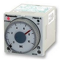
PM4HA-H-24VS
Manufacturer Part Number
PM4HA-H-24VS
Description
TIMER, MULTIFUNCTION, SCREW, 24VDC
Manufacturer
PANASONIC EW
Datasheet
1.PM4HA-H-24VS.pdf
(14 pages)
Specifications of PM4HA-H-24VS
Contact Configuration
DPDT
Nom Input Voltage
24V
Delay Time Range
1s To 500h
Adjustment Type
Knob
Relay Mounting
Panel
Svhc
No SVHC (15-Dec-2010)
Coil Voltage Vac Nom
24V
Coil Voltage Vdc
RoHS Compliant


Notes for PM4H series
MODES & TIME SETTING
1) Operation mode setting [PM4H-A]
8 operation modes are selectable with
operation mode selector.
Turn the operation mode selector with
screw driver.
Operation mode is shown up through the
window above the mode selector. The
marks are
Turn the mode selector to the mark until
you can check by clicking sound.
Confirm the mode selector position if it is
correct.
If the position is not stable, the timer
might mis-operate.
How to use “Stop ring” [PM4H series]
1) Fixed time setting
Set the desired time and put 2 stop rings
together.
Insert the rings into stopper to fix the
time.
2) Fixed time range setting
Example: Time range 20s to 30s.
DATA
Load control life
Shorter time value setting
Set the dial to 20s.
Place the stop ring at the right side of
stopper.
ON
Shorter time value
,
0
FL
20
,
SEC
FO
,
OF1
,
SF
,
OS
,
OF2
Stopper
,
OC
.
Stop ring
2) Time setting [common]
16 time ranges are selectable between
1s to 500h.
Turn the time range selector with the
screw driver.
Clockwise turning increases the time
range, and Counter-clockwise turning
decrease the time range.
Confirm the range selector position if it is
correct.
• Load life curve (PM4H-A, PM4H-S, PM4H-W)
Stop ring (2 pcs)
Longer time value setting
Set the dial to 30s.
Place the stop ring at the left side of
stopper.
1,000
100
10
0
1
02/2003
Longer time value
250V AC Resistive load (cosφ=0.4)
0
2
250V AC Resistive load (cosφ=1)
Switching capacity (A)
SEC
3
30
4
Set dial
5
Stopper
6
3) Time setting [common]
To set the time, turn the set dial to a
desired time within the range.
Instantaneous output will be on when the
dial is set to “0”.
When the instantaneous output is used,
the dial should be set under “0” range.
(Instantaneous output area)
When power supply is on, the time
range, setting time and operation mode
cannot be changed.
Turn off the power supply or a reset sig-
nal is applied to set the new operation
mode.
• Load life curve (PM4H-M)
100
10
0
265V•130V AC
cosφ=0.4
1
2
Set range
Switching capacity (A)
3
265V•130V AC cosφ=1
4
5
6
7
25
Related parts for PM4HA-H-24VS
Image
Part Number
Description
Manufacturer
Datasheet
Request
R

Part Number:
Description:
Analog Timer - PM4HA, Multi-function, DIN48, 8 Modes, Screw, 1 Sec - 500 Hr., 2 Form C, 100-240V AC
Manufacturer:
PANASONIC EW


Part Number:
Description:
TIMER RELAY ANALOG 24VAC/DC 11P
Manufacturer:
Panasonic Electric Works
Datasheet:
Part Number:
Description:
TIMER ANALOG MULTI 12VDC SCREW
Manufacturer:
Panasonic Electric Works
Datasheet:
Part Number:
Description:
TIMER RELAY ANALOG 24VAC/DC SCRW
Manufacturer:
Panasonic Electric Works
Datasheet:
Part Number:
Description:
TIMER RELAY ANALOG MULT 240VAC
Manufacturer:
Panasonic Electric Works
Datasheet:
Part Number:
Description:
TIMER ANALOG MULTI 12VDC 11PIN
Manufacturer:
Panasonic Electric Works
Datasheet:
Part Number:
Description:
TIMER RELAY ANALOG 240VAC SCREW
Manufacturer:
Panasonic Electric Works
Datasheet:

Part Number:
Description:
Manufacturer:
Panasonic Electric Works
Datasheet:

Part Number:
Description:
SIGNAL RELAY, DPDT, 5VDC, 2A, PC BOARD
Manufacturer:
PANASONIC EW
Datasheet:


Part Number:
Description:
PHOTOMOS RELAY, 60VDC, 400mA
Manufacturer:
PANASONIC EW
Datasheet:

Part Number:
Description:
PHOTOMOS RELAY, 400V, 150mA
Manufacturer:
PANASONIC EW
Datasheet: