PM4HA-H-24VS PANASONIC EW, PM4HA-H-24VS Datasheet - Page 13
PM4HA-H-24VS
Manufacturer Part Number
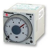
PM4HA-H-24VS
Description
TIMER, MULTIFUNCTION, SCREW, 24VDC
Manufacturer
PANASONIC EW
Datasheet
1.PM4HA-H-24VS.pdf
(14 pages)
Specifications of PM4HA-H-24VS
Contact Configuration
DPDT
Nom Input Voltage
24V
Delay Time Range
1s To 500h
Adjustment Type
Knob
Relay Mounting
Panel
Svhc
No SVHC (15-Dec-2010)
Coil Voltage Vac Nom
24V
Coil Voltage Vdc
RoHS Compliant


100 to 240V AC, 24V AC type
DC type
CAUTIONS
1. Terminal connections
1) Refer to wiring diagram before termi-
nal connections.
2) Use the screw terminal type for flush
mounting.
For using 8 pin type, use the timer with
screw terminal socket (AT8-RR) or 8 pin
cap (AD8-RC).
For using 11 pin type, use the timer with
11 pin cap (AT8-DP11).
Do not solder directly the pin of the timer
for connection.
3) The connection to power supply
Prevent inductive or residual voltages
generating between the power supply
terminals after the power is off.
(If the power supply cables are routed
parallel to the high voltage or power
cables, an inductive voltage will be gen-
erated between the power supply termi-
nals.)
On the DC type, keep the voltage within
the allowable operating voltage range
with ripple rate of 20% or less.
Apply the power supply voltage at once
through the switch or relay contacts. If
the voltage is gradually applied, the timer
may time up or power supply reset may
not operate regardless of setting time.
4) The control output load must be less
than the rated load capacity of the relay
contacts.
26
PM4H-A
PM4H-F11R
PM4H-S
PM4H-M
PM4H-W
PM4H-SD
PM4H-F8
PM4H-F8R
PM4H-A
PM4H-F11R
PM4H-S
PM4H-M
PM4H-W
PM4H-F8
PM4H-F8R
Type
Type
Connect the
terminal
the power source.
Connect the
terminal
the power source.
Connect the
terminal
negative (–), the
terminal
positive (+).
Connect the
terminal
negative (–), the
terminal
positive (+).
Pin
Pin
-
-
to
to
to
to
to
to
Connect the
terminal z-x to
the power source.
Connect the
terminal x to
negative (–), the
terminal z to
positive (+).
Screw terminal
Screw terminal
2. Input connections
1) If the circuits is connected as in Fig. A,
the internal circuits must be broken. Be
sure to connect the circuit as in Fig. B.
Especially, for customer who has been
used PM48A (Conventional type), be
sure to check if the new circuit for PM4H
timer is corrected as in Fig. B.
2) Since the PM4H timers use a trans-
formerless power supply system, the
input equipment must use the power
supply transformer in which the sec-
ondary side is not grounded with the pri-
mary and secondary sides insulated, in
order to prevent interference of the
power supply circuit when connecting the
external input circuit.
Be sure not to use an autotransformer.
3) Be sure not to use terminal
common terminal of the operation signal
as shown in Fig. A. Otherwise, the inter-
nal circuit of the timer may be damaged.
Use terminal
as shown in Fig. B.
4) When one input signal is simultane-
ously applied to more than one timer, be
sure to avoid the wiring shown in Fig. C.
Otherwise, the short-circuit current will
flow and cause damage. Be sure to align
the polarity of the power supply as
shown in Fig. D.
Input terminals
T,Y,U
Rated
operating
voltage
Rated
operating
voltage
Fig. A
PM4H-A
No good
as the common terminal
Good
02/2003
Contact input
(or non-contact input)
Input terminals
T,Y,U
Contact input
(or non-contact
input)
Fig. B
PM4H-A
Fig. A
Fig. B
as the
5) Terminal
should be connected as the operation
signal input. Connect terminals
(screw terminal
input. Connect terminals
terminal
sure not to connect with other terminals
and apply excessive voltage. The inter-
nal circuit will be damaged.
6) The input wiring other than the power
supply circuit should avoid these condi-
tions, high-voltage wiring and parallel
wiring with power wire. Wire in short with
using the sealed-wire or metal wiring
tube.
7) For operation signal, reset and stop
input, use gold-plated contact with high
reliability. Since contact bouncing causes
errors in the operation, use an input con-
tact less bounce time.
8) Keep the minimum signal input time
over 0.05 s.
3. Input signal conditions
1) Connections of contact input
Use gold-plated contacts with high-relia-
bility. The bounce time at the contacts
causes errors in the timer operation time.
Accordingly, use signal input contact
whose bounce time is short. The resis-
tance when shorted should be less than
1kΩ, and when open resistance should
be more than 100kΩ.
Rated
operating voltage
Rated
operating voltage
Notes for PM4H series
- ) for stop signal input. Be
-
No good
Good
(screw terminal
- ) for reset signal
Contact input
(or non-contact input)
Contact input
(or non-contact input)
-
(screw
Fig. C
Fig. D
-
- )
Related parts for PM4HA-H-24VS
Image
Part Number
Description
Manufacturer
Datasheet
Request
R

Part Number:
Description:
Analog Timer - PM4HA, Multi-function, DIN48, 8 Modes, Screw, 1 Sec - 500 Hr., 2 Form C, 100-240V AC
Manufacturer:
PANASONIC EW


Part Number:
Description:
TIMER RELAY ANALOG 24VAC/DC 11P
Manufacturer:
Panasonic Electric Works
Datasheet:
Part Number:
Description:
TIMER ANALOG MULTI 12VDC SCREW
Manufacturer:
Panasonic Electric Works
Datasheet:
Part Number:
Description:
TIMER RELAY ANALOG 24VAC/DC SCRW
Manufacturer:
Panasonic Electric Works
Datasheet:
Part Number:
Description:
TIMER RELAY ANALOG MULT 240VAC
Manufacturer:
Panasonic Electric Works
Datasheet:
Part Number:
Description:
TIMER ANALOG MULTI 12VDC 11PIN
Manufacturer:
Panasonic Electric Works
Datasheet:
Part Number:
Description:
TIMER RELAY ANALOG 240VAC SCREW
Manufacturer:
Panasonic Electric Works
Datasheet:

Part Number:
Description:
Manufacturer:
Panasonic Electric Works
Datasheet:

Part Number:
Description:
SIGNAL RELAY, DPDT, 5VDC, 2A, PC BOARD
Manufacturer:
PANASONIC EW
Datasheet:


Part Number:
Description:
PHOTOMOS RELAY, 60VDC, 400mA
Manufacturer:
PANASONIC EW
Datasheet:

Part Number:
Description:
PHOTOMOS RELAY, 400V, 150mA
Manufacturer:
PANASONIC EW
Datasheet: