SF2-24V PANASONIC EW, SF2-24V Datasheet - Page 4
SF2-24V
Manufacturer Part Number
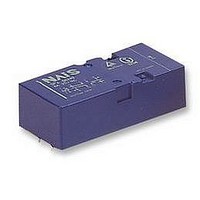
SF2-24V
Description
RELAY, FORCED CONTACT, DPCO, 24VDC
Manufacturer
PANASONIC EW
Datasheet
1.SF2-24V.pdf
(5 pages)
Specifications of SF2-24V
Coil Voltage Vdc Nom
24V
Coil Resistance
1.152kohm
Contact Current Max
6A
Contact Voltage Ac Nom
250V
Contact Voltage Dc Nom
30V
No. Of Poles
2
Relay Mounting
PC Board
External Width
25mm
Lead Free Status / RoHS Status
Lead free / RoHS Compliant
Available stocks
Company
Part Number
Manufacturer
Quantity
Price
Company:

Part Number:
SF2-24V
Manufacturer:
SIEMENS
Quantity:
12 000


SF
THE OPERATION OF SF RELAYS (when contacts are welded)
SF relays work to maintain a normal operating state even when overloading or short-circuit currents occur. It is also easy to
include weld detection and safety circuits in the design to ensure safety even if contacts weld.
1) 2a2b Type
If the form “b” contacts (No. 1 or 3) weld, the armature becomes non-operational and the contact gap of the two form “a” contacts is
maintained at greater than 0.5 mm
If the form “a” contacts (No. 2 or 4) weld, the armature becomes non-operational and the gap between the two form “b” contacts is
maintained at greater than 0.5 mm
The table below shows the state of the other contacts when the current through the welded form “a” contact is 0 V and the rated
voltage is applied through the form “b” contact.
No.4
No.3
No.4
No.3
No.4
No.3
Terminal No.
Contact No.
Contact Operation Table
Form “b” Contact Weld
Form “a” Contact Weld
Non-energized
11–12
No.1
Energized
No.2
7–8
No.3
5–6
9–10
No.4
No.1
No.2
No.1
No.2
No.1
No.2
.020
.020
inch. Reliable isolation is thus ensured.
inch. Reliable isolation is thus ensured.
All Rights Reserved © COPYRIGHT Matsushita Electric Works, Ltd.
Note: Contact gaps are shown at the initial state.
If the contacts change state owing to loading/breaking
it is necessary to check the actual loading.
Contact No.
terminal
Welded
No.4
No.3
No.4
No.3
Non-energized (when no. 2 contact is welded)
No.
Energized (when no. 1 contact is welded)
Contact No.
1
2
3
4
>0.5
>0.5
1
State of other contacts
>0.5
>0.5
2
>0.5
>0.5
3
No.1
No.2
No.1
No.2
>0.5
>0.5
4
If the No. 1 contact welds.
A gap of greater than 0.5 mm
maintained at each of the two form “a” contacts
(No. 2 and 4).
If the No. 2 contact welds.
Each of the two form “b” contacts (No. 1 and 3)
maintains a gap of greater than 0.5 mm
inch.
Empty cells: either closed or open
>0.5: contact gap is kept at
min. 0.5 mm
.020 inch
.020 inch
is
.020
Related parts for SF2-24V
Image
Part Number
Description
Manufacturer
Datasheet
Request
R

Part Number:
Description:
[TYPE-2] 16-CH 13.780"(350MM) PNP 20MM P-P SAFETY LIGHT CURTAIN
Manufacturer:
PANASONIC EW
Part Number:
Description:
[TYPE-2] 80-CH 64.173"(1630MM) NPN 20MM P-P SAFETY LIGHT CURTAIN(SPARK PROTECTION)
Manufacturer:
PANASONIC EW
Part Number:
Description:
[TYPE-2] 88-CH 70.472"(1790MM) NPN 20MM P-P SAFETY LIGHT CURTAIN(SPARK PROTECTION)
Manufacturer:
PANASONIC EW

Part Number:
Description:
RELAY, FORCED CONTACT, DPCO, 12VDC
Manufacturer:
PANASONIC EW
Datasheet:


Part Number:
Description:
Relay; Hybrid; Sfty; Cur-Rtg 100mA; Ctrl-V 24DC; Plug-in; cULus, CE, OSHA/ANSI
Manufacturer:
Panasonic Electric Works
Datasheet:

Part Number:
Description:
SF MB KIT FOR K FRAME-DONOT USE W/MILLE CB
Manufacturer:
SQUARE D

Part Number:
Description:
SIGNAL RELAY, DPDT, 5VDC, 2A, PC BOARD
Manufacturer:
PANASONIC EW
Datasheet:


Part Number:
Description:
PHOTOMOS RELAY, 60VDC, 400mA
Manufacturer:
PANASONIC EW
Datasheet:

Part Number:
Description:
PHOTOMOS RELAY, 400V, 150mA
Manufacturer:
PANASONIC EW
Datasheet: