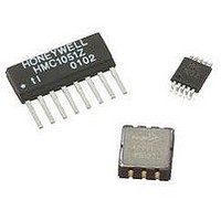
HMC6352 Honeywell Microelectronics & Precision Sensors, HMC6352 Datasheet - Page 4

HMC6352
Manufacturer Part Number
HMC6352
Description
Magnetic Sensor
Manufacturer
Honeywell Microelectronics & Precision Sensors
Datasheet
1.HMC6352.pdf
(13 pages)
Specifications of HMC6352
Msl
MSL 3 - 168 Hours
Terminal Type
PCB
Supply Voltage
5.2V
Sensor Terminals
SMD
Supply Current
10mA
Magnetic Field Max
0.75G
Axis Configuration
Two
Magnetic Field Min
0.10G
Available stocks
Company
Part Number
Manufacturer
Quantity
Price
Company:
Part Number:
HMC6352
Manufacturer:
honeywell
Quantity:
12 800
Part Number:
HMC6352
Manufacturer:
HITTITE
Quantity:
20 000
Company:
Part Number:
HMC6352-TR
Manufacturer:
HIROSE
Quantity:
670
HMC6352
address byte designates if the operation is a read (LSb=1) or a write (LSb=0). At the 9
device will issue the ACK (or NACK). Following these bus events, the master will send data bytes for a write operation, or
the slave will transmit back data for a read operation. All bus transactions are terminated with the master issuing a stop
sequence.
The following timing diagram shows an example of a master commanding a HMC6352 (slave) into sleep mode by sending
the “S” command. The bottom two traces show which device is pulling the SDA line low.
I
SDA and SCL lines as appropriate to allow the slave device to manipulate these lines. In a software implementation, care
must be taken to perform these tasks in code.
Command Protocol
The command protocol defines the content of the data (payload) bytes of I
device (HMC6352).
After the master device sends the 7-bit slave address, the 1-bit Read/Write, and gets the 1-bit slave device acknowledge
bit returned; the next one to three sent data bytes are defined as the input command and argument bytes. To conserve
data traffic, all response data (Reads) will be context sensitive to the last command (Write) sent. All write commands shall
have the address byte least significant bit cleared (factory default 42(hex)). These commands then follow with the ASCII
command byte and command specific binary formatted argument bytes in the general form of:
(Command ASCII Byte) (Argument Binary MS Byte) (Argument Binary LS Byte)
The slave (HMC6352) shall provide the acknowledge bits between each data byte per the I
reads are done by sending the address byte (factory default 43(hex)) with the least significant bit set, and then clocking
back one or two response bytes, last command dependant. For example, an “A” command prompts the HMC6352 to
make a sensor measurement and to route all reads for a two byte compass heading or magnetometer data response.
Then all successive reads shall clock out two response bytes after sending the slave address byte. Table 1 shows the
HMC6352 command and response data flow.
4
2
C bus control can be implemented with either hardware logic or in software. Typical hardware designs will release the
M_SDA
M_SDA
S_SDA
S_SDA
SDA
SDA
SCL
SCL
START
START
START
Write to This I
0
0
0
1
1
1
42(hex)
0
0
0
2
0
0
0
C Address
0
0
0
0
0
0
1
1
1
0
0
0
ACK
ACK
ACK
0
0
0
1
1
1
0
0
0
2
C protocol sent by the master, and the slave
Command
1
1
1
“S”
0
0
0
th
0
0
0
clock pulse, the recieving slave
1
1
1
2
C protocol. Response byte
1
1
1
www.honeywell.com
ACK
ACK
ACK
STOP
STOP
STOP


