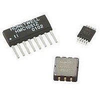
HMC6352 Honeywell Microelectronics & Precision Sensors, HMC6352 Datasheet - Page 8

HMC6352
Manufacturer Part Number
HMC6352
Description
Magnetic Sensor
Manufacturer
Honeywell Microelectronics & Precision Sensors
Datasheet
1.HMC6352.pdf
(13 pages)
Specifications of HMC6352
Msl
MSL 3 - 168 Hours
Terminal Type
PCB
Supply Voltage
5.2V
Sensor Terminals
SMD
Supply Current
10mA
Magnetic Field Max
0.75G
Axis Configuration
Two
Magnetic Field Min
0.10G
Available stocks
Company
Part Number
Manufacturer
Quantity
Price
Company:
Part Number:
HMC6352
Manufacturer:
honeywell
Quantity:
12 800
Part Number:
HMC6352
Manufacturer:
HITTITE
Quantity:
20 000
Company:
Part Number:
HMC6352-TR
Manufacturer:
HIROSE
Quantity:
670
HMC6352
these offset values are added to the sensor offset values computed by the set/reset routine to convert the raw
magnetometer data to the compensated magnetometer data. These values are written into EEPROM addresses 01(hex)
to 04 (hex) and loaded to RAM on the power up. These offsets are in ADC counts applied to the 10-bit ADC raw
magnetometer data. Most offset MSB values will likely be zero filled or complemented.
Time Delay
The EEPROM time delay byte is the binary value of the number of milliseconds from the time a measurement request was
commanded and the time the actual measurements are made. The default value is 01(hex) for no delay. Extra
measurement delays maybe desired to allow for amplifier stabilization from immediate HMC6352 power-up or for external
filter capacitor selection that limits the bandwidth and time response of the amplifier stages. This value is written into
EEPROM address 05(hex) and loaded to RAM on the power up.
Measurement Summing
This EEPROM summed measurement byte permits designers/users to back average or data smooth the output data
(heading, magnetometer values) to reduce the amount of jitter in the data presentation. The default value is 04(hex) which
is four measurements summed. A value of 00(hex) would be no summing. Up to 16 sets of magnetometer data may be
selected for averaging. This slave address is written into EEPROM address 06(hex) and loaded to RAM on the power up.
Software Version
This EEPROM software version number byte contains the binary value of the programmed software. Values of 01(hex)
and beyond are considered production software.
Timing Requirements
Table 3 contains the time delays required by HMC6352 upon receipt of the command to either perform the commanded
task or to have the response available on the I
Command and Operation Mode Interactions
All commands are accepted in the standby mode. Honeywell strongly recommends using this mode during the initial setup
stage. Setting up of the HMC6352 operation mode and its slave address are typical set up examples. Although execution
of all commands in the Query and Continuous Modes is acceptable, the completion outcome is not guaranteed.
Q: How to Read Data from HMC6352?
A:
8
In Standby Mode - Use “A” command.
In Query Mode - Send 43(hex) slave address to read data and clock out the two register data bytes for heading.
An initial “A” command is needed to update the heading after each read.
ASCII (hex)
Command
W (57)
O (4F)
w (77)
G (47)
S (53)
C (43)
E (45)
L (4C)
A (41)
g (67)
r (72)
Byte
Description
Write to EEPROM
Read from EEPROM
Write to RAM Register
Read from RAM Register
Enter Sleep Mode (Sleep)
Exit Sleep Mode (Wakeup)
Update Bridge Offsets (S/R Now)
Enter User Calibration Mode
Exit User Calibration Mode
Save Op Mode to EEPROM
Get Data. Compensate and Calculate
New Heading
Table 3 – Interface Command Delays
2
C bus.
Time Delay (µsec)
14000
6000
6000
100
125
70
70
70
70
10
10
www.honeywell.com


