FE-MLS8C PEPPERL & FUCHS, FE-MLS8C Datasheet - Page 3
FE-MLS8C
Manufacturer Part Number
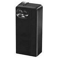
FE-MLS8C
Description
Photoelectric Sensor
Manufacturer
PEPPERL & FUCHS
Type
Fiber Opticr
Specifications of FE-MLS8C
Output Current
10A
Sensor Output
Relay
Sensor Housing
Rectangular
Peak Reflow Compatible (260 C)
No
Output Type
Relay
Sensor Input
Optical
Supply Voltage Max
132VAC
Sensing Range Max
12m
Body Style
Rectangular
Brand/series
FE-MLS8C
Function
Proximity
Ip Rating
IP67
Output
Relay
Primary Type
Photoelectric
Range, Measurement
12 m
Sensing Mode
Retro-Reflective
Technology
Photoelectric
Termination
Screw
Voltage, Supply
132 VAC
Leaded Process Compatible
No
Rohs Compliant
No
Lead Free Status / RoHS Status
Contains lead / RoHS non-compliant


FE-MLS8C Wiring and Alignment
1. Remove the rear housing cover.
2a. Connect the load and load supply (common)
2b. Solid state relay connections shown below.
3. Connect AC power (through the conduit opening)
4. Set the mode selector switch to the light
5. Apply power. The alignment indicator light
ELECTRICAL CONTACT RATING
LED(s)
POWER CONSUMPTION
MECHANICAL LIFE OF RELAY
OPERATING MODE
ELECTROMAGNETIC
COMPATIBILITY COMPLIANCE
PROTECTION (IEC)
LIGHT SOURCE
TEMPERATURE RANGE
HOUSING MATERIAL
ELECTRICAL CONNECTION
MLS8C/9C Series Specifications
PEPPERL+FUCHS
to selected terminals. Standard relay
connections shown below.
to the “LINE” terminals. The white and black
input wires must be connected to the proper
terminals. See the control nameplate for correct
line volage.
operate (L.O.) position.
visible at the top of the control will remain OFF
with no reflector present.
C 1
C 1
NO 1
NO 1
LENS
NC 1
Terminations
Series Specifications
NC 2
NO 2
Pepperl+Fuchs Inc. • 1600 Enterprise Parkway • Twinsburg, Ohio 44087-2245 • www.am.pepperl-fuchs.com
Telephone (330) 486-0001 • FAX (330) 405-4710 • E-Mail: sales@us.pepperl-fuchs.com
C 2
Glass reinforced polycarbonate
Line
Line
®
500,000 operations
NEMA ICS5-2000
Light on/dark on
-40ºF to +158ºF
Infrared LED
See page 6
115V/10A
Plastic
Yes (1)
≤5VA
IP67
Terminal
connection
6. Position the reflector opposite the lens. The
7. Center the reflector in the beam (by watching
8. Block the invisible beam with the object to be
9. Fully tighten the mounting bolts, and again
10. If direct On-Off dark operation is desired (relay
11. Insert optional function card firmly (if used)
12. Replace cover and tighten both screws.
indicator will turn On when control and reflector
are in alignment.
the indicator as the reflector is moved up,
down, left and right). Use adhesive or a #8
screw (for the 3-inch disc) to mount the
reflector.
detected. When the beam is blocked, the
indicator will be Off.
block the beam to recheck alignment.
energized when the beam is blocked), move
the mode selector switch to the dark operate
(D.O.) position.
and adjust pots as required.
FE-MLS8C and FE-MLS9C
Functional Block Diagram
Photoelectric Sensors
D.O.
C 1 NO 1 NC 1 NC 2 NO 2 C 2
Relay
For Optional Card
Lens
L.O.
Pin Connect
Receiver
Photo
Terminations
Amplifier
Supply
Power
OSC
Pulsing
L.E.D.
Line
Indicator
L.E.D.
Red
535
Related parts for FE-MLS8C
Image
Part Number
Description
Manufacturer
Datasheet
Request
R


Part Number:
Description:
WE77/EX-1 230V, PEPPERL + FUCHS, SWITCH ISOLATOR 230V
Manufacturer:
PEPPERL & FUCHS
Datasheet:
Part Number:
Description:
Rotary Encoders - Absolute
Manufacturer:
PEPPERL & FUCHS


Part Number:
Description:
LED Pilot Light
Manufacturer:
PEPPERL & FUCHS
Datasheet:

Part Number:
Description:
LED Pilot Light
Manufacturer:
PEPPERL & FUCHS
Datasheet:
Part Number:
Description:
LED Pilot Light
Manufacturer:
PEPPERL & FUCHS
Datasheet:
Part Number:
Description:
LED Pilot Light
Manufacturer:
PEPPERL & FUCHS
Datasheet: