MA3 BANNER ENGINEERING, MA3 Datasheet - Page 16
MA3
Manufacturer Part Number
MA3
Description
AMPLIFIER FOR SP100 SERIES SENSORS
Manufacturer
BANNER ENGINEERING
Datasheet
1.MA3.pdf
(20 pages)
Specifications of MA3
Output Current
150mA
Sensor Output
Sink
Supply Voltage Range Dc
10V To 30V
Leaded Process Compatible
No
Peak Reflow Compatible (260 C)
No
Available stocks
Company
Part Number
Manufacturer
Quantity
Price
Company:

Part Number:
MA3-242LH+
Manufacturer:
MINI
Quantity:
2 532
Company:
Part Number:
MA30-A(TX)
Manufacturer:
NS
Quantity:
2 175
Part Number:
MA30-A(TX)
Manufacturer:
PANASONIC/松下
Quantity:
20 000
Company:
Part Number:
MA300014
Manufacturer:
Microchip Technology
Quantity:
135
Company:
Part Number:
MA300014
Manufacturer:
MICROCHIP
Quantity:
12 000
Company:
Part Number:
MA300015
Manufacturer:
MICROCHIP
Quantity:
12 000
Part Number:
MA3020-(TX)
Manufacturer:
PANASONIC/松下
Quantity:
20 000
Part Number:
MA3020-TX
Manufacturer:
PANASONIC/松下
Quantity:
20 000
Part Number:
MA3024-(TW)
Manufacturer:
PANASONIC/松下
Quantity:
20 000
Part Number:
MA3024-X
Manufacturer:
PANASON
Quantity:
20 000


16
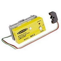
Model MPC3-DB Demo Board
The MPC3-DB is a battery-powered demonstration/testing board
which is available to help in evaluating the MPC3 and its sensor(s).
The demo board includes a plug-in MPC3 and indicator LEDs for
both outputs, plus the "AID™" indicator, a sensitivity potentiometer,
and a 4-pin terminal strip to which the LED and receiver phototran-
sistor may be connected.
The MPC3-DB is powered by 3 "AA" penlight batteries. (Yes,
batteries are included!!!) This is a very simple and inexpensive way
to become familiar with the characteristics of the MPC3, and to
evaluate the sensors to be used with the MPC3.
Functional Schematic, MICRO-AMP MPC3
Hookup Diagram, MICRO-AMP MPC3
* U.S. Patent #4598198
**U.S. Patent #4356393
Circuit Description
The functional schematic shows the MPC3 powered by 5V
dc at pins #1 and #3. An internal emitter oscillator
generates 30 microsecond pulses at a rate of approximately
400Hz, which are fed to the emitter at pin #5. These emitter
current pulses are controlled automatically by a patented*
power-limiting circuit that adjusts to the emitter and to the
frequency in use.
The phototransistor receives the light pulses from the LED,
either directly or by reflection from an object, and sends
them to the input (pin #4) via the sensitivity adjustment
resistor (or potentiometer). These low-level signals are
amplified, separated from the emitted light, and then
detected by the threshold detector. The resultant logic-
level pulses are then gated synchronously with the oscilla-
tor output (to eliminate noise and interference) and de-
modulated. The demodulated output is then buffered and
inverted, and brought to the output pins #7 and #8. In
addition, a small amount of hysteresis is fed back to the
threshold detector to assure clean, bounce free output
switching. The amplified signal is also fed through a
negative peak detector and to a voltage-controlled oscilla-
tor whose output frequency is directly proportional to
signal strength. This is the patented** Banner "AID™"
feature which flashes the LED indicator at a rate which is
proportional to the strength of the received light signal
(excess gain).
Dimensions, MPC3
Related parts for MA3
Image
Part Number
Description
Manufacturer
Datasheet
Request
R

Part Number:
Description:
MA3-19859 PLUG IN AMPLIFIER W/10in CABLE & CONN./6 CABLE
Manufacturer:
BANNER ENGINEERING
Part Number:
Description:
MA3-4 HG PLUG IN AMPLIFIER
Manufacturer:
BANNER ENGINEERING
Datasheet:

Part Number:
Description:
Photoelectric Sensor
Manufacturer:
BANNER ENGINEERING
Datasheet:

Part Number:
Description:
Photoelectric Sensor
Manufacturer:
BANNER ENGINEERING
Datasheet:
Part Number:
Description:
LEDIR70XD4-XM-81039 MAX INTENS STROBE ONLY NO BANNER MARKS
Manufacturer:
BANNER ENGINEERING
Part Number:
Description:
M18SP6DL-72225 LABELED MOELLER NO BANNER MARKINGS BULK PACK
Manufacturer:
BANNER ENGINEERING
Part Number:
Description:
Photoelectric Sensor
Manufacturer:
BANNER ENGINEERING
Datasheet:

Part Number:
Description:
Programmable Indicator Light
Manufacturer:
BANNER ENGINEERING
Datasheet:
Part Number:
Description:
INDICATOR LED PANEL 50MM GRN/RED/YEL 30V
Manufacturer:
BANNER ENGINEERING
Datasheet:
Part Number:
Description:
Programmable Indicator Light
Manufacturer:
BANNER ENGINEERING
Datasheet: