XF2M-2015-1A Omron, XF2M-2015-1A Datasheet - Page 17
XF2M-2015-1A
Manufacturer Part Number
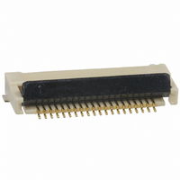
XF2M-2015-1A
Description
CONN FPC 20POS 0.5MM PITCH SMD
Manufacturer
Omron
Series
XF2Mr
Specifications of XF2M-2015-1A
Contact Plating
Gold
Connector Type
Top and Bottom Contacts
Number Of Positions
20
Pitch
0.020" (0.50mm)
Ffc, Fcb Thickness
0.30mm
Height Above Board
0.083" (2.10mm)
Mounting Type
Surface Mount, Right Angle
Cable End Type
Straight
Termination
Solder
Locking Feature
Rotary Lock, Backlock
Contact Finish
Gold
Contact Finish Thickness
5.9µin (0.15µm)
Operating Temperature
-30°C ~ 85°C
Current Rating
0.500A
Voltage Rating
50V
Housing Material
Liquid Crystal Polymer (LCP)
Product Type
PCB
Number Of Positions / Contacts
20
Mounting Angle
Straight
Mounting Style
Through Hole
Contact Material
Spring Copper Alloy / Nickel Substrate
Termination Style
Solder Pin
Gender
Receptacle
Pitch Spacing
0.5mm
No. Of Contacts
20
No. Of Rows
1
Ffc/fpc Thickness
0.3mm
Contact Termination
Surface Mount Vertical
Lead Free Status / RoHS Status
Lead free / RoHS Compliant
Features
-
Lead Free Status / Rohs Status
Lead free / RoHS Compliant
Other names
OR719TR
XF2M20151A
XF2M20151A
Available stocks
Company
Part Number
Manufacturer
Quantity
Price
Company:

Part Number:
XF2M-2015-1A
Manufacturer:
OMRON
Quantity:
12 000
Part Number:
XF2M-2015-1A
Manufacturer:
OMRON/欧姆龙
Quantity:
20 000


Greater Freedom in Board Design with a Bottom
Wall and the Smallest On-board Area in the Industry
• Smallest on-board area and volume in the industry.
• Low on-board profile of only 1.2 mm.
• Highest board design surface efficiency in the industry with
• Construction with secure slider locking mechanism.
• Applicable FPC thickness of 0.3 mm.
■ Ratings and Specifications
XF2L-@@@5-1A
■ Dimensions
Table of Dimensions
Upper-contact Models
XF2L-@@@5-1@
Rated current
Rated voltage
Contact resistance
Insulation resistance 100 M Ω min. (at 250 V DC)
Withstand voltage
Insertion tolerance
Ambient operating
temperature
note 2.)
ZIF Slide-locking Connector
(0.5-mm Pitch)
RoHS Compliant
a bottom wall preventing terminal exposure.
Pins
(See
1.05
10
12
13
18
21
26
30
4
6
7
8
9
1
XF2L- @@25-1 (Upper-contact Models)
XF2L- @@35-1 (Lower-contact Models)
(See note 1.)
XF2L-0425-1@
XF2L-0625-1@
XF2L-0725-1@
XF2L-0825-1@
XF2L-0925-1@
XF2L-1025-1@
XF2L-1225-1@
XF2L-1325-1@
XF2L-1825-1@
XF2L-2125-1@ 10.0 14.4 15.4 11.1 14.38 15.38 13.78 15.78
XF2L-2625-1@ 12.5 16.9 17.9 13.6 16.88 17.88 16.28 18.28
XF2L-3025-1@ 14.5 18.9 19.9 15.6 18.88 19.88 18.28 20.28
Model
0.5
0.5 A AC/DC
50 V AC/DC
30 m Ω max.
(at 20 mV DC max., 100 mA max.)
250V AC for 1 min.
(leakage current: 1 mA max.)
20 times
− 30 to 85 ° C
(with no icing or condensation)
D
B
A
C
D
A
1.5
2.5
3.0
3.5
4.0
4.5
5.5
6.0 10.4 11.4
8.5 12.9 13.9
0.2
B
5.9
6.9
7.4
7.9
8.4
8.9
9.9 10.9
C
6.9
7.9
8.4
8.9
9.4
9.9
D
2.6
3.6
4.1
4.6
5.1
5.6
6.6
7.1 10.38 11.38
9.6 12.88 13.88 12.28 14.28
5.88
6.88
7.38
7.88
8.38
8.88
9.88 10.88
0.75
E
2.5 min.
0.35
0.5
6.88
7.88
8.38
8.88
9.38
9.88
Applicable FPC Dimensions
F
3.05
±0.1
±0.03
3.05
3.45
3.45
5.28
6.28
6.78
7.28
7.78
8.28 10.28
9.28 11.28
9.78 11.78
G
(D−0.1)
1.2
1.2
0.5
A
7.28
8.28
8.78
9.28
9.78
H
±0.05
±0.05
±0.05
With slider open
With slider open
■ Materials and Finish
XF2L-@@@5-1A
Lower-contact Models
Reinforcement board
Ordering
Housing
Slider
Contacts
Hold-down Spring copper alloy/fused-tin plating (1.5 μ m)
1.35 (Effective
interface length)
T=0.3±0.03
(Conductive plating)
note 2.)
4.55
4.55
Pins
(See
10
12
13
15
18
19
20
22
24
30
(See note.)
5
6
7
8
Model
(5)
(See note 1.)
XF2L-0535-1@
XF2L-0635-1@
XF2L-0735-1@
XF2L-0835-1@
XF2L-1035-1@
XF2L-1235-1@
XF2L-1335-1@
XF2L-1535-1@
XF2L-1835-1@
XF2L-1935-1@
XF2L-2035-1@
XF2L-2235-1@ 10.5 14.9 15.9 11.6 14.88 15.88 14.28 16.28
XF2L-2435-1@ 11.5 15.9 16.9 12.6 15.88 16.88 15.28 17.28
XF2L-3035-1@ 14.5 18.9 19.9 15.6 18.88 19.88 18.28 20.28
0.55
LCP resin (UL94V-0)/natural
LCP resin (UL94V-0)/black
Spring copper alloy/nickel substrate (2 μ m),
gold-plated contacts (0.15 μ m)
Model
1.34
(Upper-contact Models)
±0.1
±0.1
1
±0.1
Note. Use polyimide and thermoset adhesive for
XF2L
PCB Mating Dimensions (Top View)
A
2.0
2.5
3.0
3.5
4.5
5.5
6.0 10.4 11.4
7.0 11.4 12.4
8.5 12.9 13.9
9.0 13.4 14.4 10.1 13.38 14.38 12.78 14.78
9.5 13.9 14.9 10.6 13.88 14.88 13.28 15.28
reinforcement film material.
B
6.4
6.9
7.4
7.9
8.9
9.9 10.9
0.5
C
7.4
7.9
8.4
8.9
9.9
±0.05
A
G
H
D
3.1
3.6
4.1
4.6
5.6
6.6
7.1 10.38 11.38
8.1 11.38 12.38 10.78 12.78
9.6 12.88 13.88 12.28 14.28
LCP resin (UL94V-0)/
brown
±0.05
F
E
±0.1
±0.1
XF2L
(Lower-contact Models)
0.25
6.38
6.88
7.38
7.88
8.88
9.88 10.88
+0.05
E
0
XF2L
7.38
7.88
8.38
8.88
9.88
F
5.78
6.28
6.78
7.28
8.28 10.28
9.28 11.28
9.78 11.78
G
7.78
8.28
8.78
9.28
H
17
Related parts for XF2M-2015-1A
Image
Part Number
Description
Manufacturer
Datasheet
Request
R

Part Number:
Description:
CONNECTOR FPC 20POS 0.3MM SMD
Manufacturer:
Omron
Datasheet:

Part Number:
Description:
CONN FPC 30POS 0.5MM PITCH SMD
Manufacturer:
Omron
Datasheet:

Part Number:
Description:
CONN FPC 32POS 0.5MM PITCH SMD
Manufacturer:
Omron
Datasheet:
Part Number:
Description:
CONN FPC 14POS 0.5MM PITCH SMD
Manufacturer:
Omron
Datasheet:

Part Number:
Description:
G6S-2GLow Signal Relay
Manufacturer:
Omron Corporation
Datasheet:
Part Number:
Description:
Compact, Low-cost, SSR Switching 5 to 20 A
Manufacturer:
Omron Corporation
Datasheet:
Part Number:
Description:
Manufacturer:
Omron Corporation
Datasheet:
Part Number:
Description:
Manufacturer:
Omron Corporation
Datasheet:
Part Number:
Description:
Manufacturer:
Omron Corporation
Datasheet:
Part Number:
Description:
Manufacturer:
Omron Corporation
Datasheet: