NZ1HS-2131-M EUCHNER, NZ1HS-2131-M Datasheet - Page 10
NZ1HS-2131-M
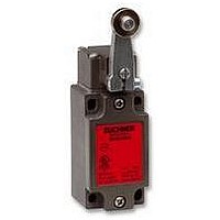
Manufacturer Part Number
NZ1HS-2131-M
Description
SAFETY SWITCH
Manufacturer
EUCHNER
Datasheet
1.NZ1HS-2131-M.pdf
(127 pages)
Specifications of NZ1HS-2131-M
Actuation Type
Lever
Operating Force Max
15N
Contact Voltage Ac Max
230V
Contact Voltage Dc Max
24V
Contact Current Ac Max
4A
Contact Current Dc Max
4A
Switch Terminals
Screw
Actuator Type
Lever Arm
Actuator Style
Lever


General
Electrical connection
On switches with cable entry there is a large space envelope for making
the electrical connection.
Modern wiring concepts increasingly utilize plug-in connections. A switch
with plug connectors can be easily replaced during servicing work. This
configuration results in short downtimes.
The safety switches NZ and TZ are available with various plug connectors.
In addition to the appropriate mating connectors, these connectors are
available with pre-assembled cables as accessories.
Switch layout
The locking arm ensures that the switch is guard locked by the solenoid.
It acts directly on the switching element ÜK; the positively driven contact
can only be closed in the locked state (see
unintentional closing) .
The position of the SK switching element is dependent on the position of
the actuator or the safety guard. This situation means that the positively
driven contacts on the SK switching element are only closed if the actuator
is in the switch head.
The position of the ÜK switching element is dependent on the position of
the actuator or the safety guard and the position of the solenoid or the
guard locking. I.e., both guard locking and positively driven contact on
the ÜK switching element can only be closed if the actuator is in the
switch head and the interlocking solenoid is controlled correspondingly.
Operating principle
The sectional drawings show the safety switch TZ in its three switch
states:
In the initial state (actuator removed/safety guard open) all positively
driven contacts (SK and ÜK) are open. The related normally open contacts
23-24 are closed and signal the state open and unlocked . Unintentional
closing of the contacts on switching element ÜK is impossible due to
the switch mechanism (see protection against unintentional closing ).
Actuator
10
Locking arm
SK
ÜK
Door open and unlocked
Locking arm
Plunger
SK
Safety circuit
Switch head
11
23
12
24
11
23
Guard locking
solenoid
12
24
protection against
ÜK
Monitoring
circuit
The plunger is released by inserting the actuator into the switch head.
The contacts 11-12 on switching element SK are closed, the contacts
23-24 are opened. The contacts 11-12 on the switching element ÜK
remain open as before, the door auxiliary contacts 23-24 for switching
element ÜK remain closed.
After the actuator has been inserted, it is possible to activate the switch's
guard locking. If the interlocking solenoid is activated, the locking arm
locks the plunger and actuates the switching element ÜK. The contacts
11-12 are closed on this switching element. The contacts 11-12 on the
switching element SK continue to remain closed. In this position the
positively driven contacts 11-12 on the two switching elements SK and
ÜK are safely locked, both door auxiliary contacts 23-24 are opened.
The actuator and the safety guard are locked. This means that the
machine connected to the safety circuit can be started.
Door closed and unlocked
Door closed and locked
SK
SK
SK
11
11
11
23
23
23
24
24
24
12
12
12
11
11
11
23
23
23
Guard locking
Guard locking
Guard locking
solenoid
solenoid
solenoid
24
24
24
ÜK
ÜK
12
12
ÜK
12
Related parts for NZ1HS-2131-M
Image
Part Number
Description
Manufacturer
Datasheet
Request
R

Part Number:
Description:
ACTUATOR
Manufacturer:
EUCHNER
Datasheet:

Part Number:
Description:
ACTUATOR
Manufacturer:
EUCHNER
Datasheet:

Part Number:
Description:
ACTUATOR
Manufacturer:
EUCHNER
Datasheet:

Part Number:
Description:
ACTUATOR
Manufacturer:
EUCHNER
Datasheet:

Part Number:
Description:
JOYSTICK SWITCH
Manufacturer:
EUCHNER
Datasheet:

Part Number:
Description:
JOYSTICK SWITCH
Manufacturer:
EUCHNER
Datasheet:

Part Number:
Description:
JOYSTICK SWITCH
Manufacturer:
EUCHNER
Datasheet:

Part Number:
Description:
JOYSTICK SWITCH
Manufacturer:
EUCHNER
Datasheet:

Part Number:
Description:
JOYSTICK SWITCH
Manufacturer:
EUCHNER
Datasheet:


Part Number:
Description:
LIMIT SWITCH, SINGLE
Manufacturer:
EUCHNER
Datasheet:

Part Number:
Description:
SAFETY SWITCH
Manufacturer:
EUCHNER
Datasheet:

Part Number:
Description:
SAFETY SWITCH
Manufacturer:
EUCHNER
Datasheet:

Part Number:
Description:
SAFETY SWITCH
Manufacturer:
EUCHNER
Datasheet:

Part Number:
Description:
SAFETY SWITCH
Manufacturer:
EUCHNER
Datasheet: