NZ1HS-2131-M EUCHNER, NZ1HS-2131-M Datasheet - Page 109
NZ1HS-2131-M
Manufacturer Part Number
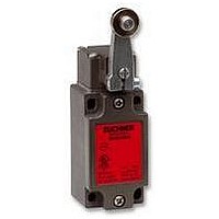
NZ1HS-2131-M
Description
SAFETY SWITCH
Manufacturer
EUCHNER
Datasheet
1.NZ1HS-2131-M.pdf
(127 pages)
Specifications of NZ1HS-2131-M
Actuation Type
Lever
Operating Force Max
15N
Contact Voltage Ac Max
230V
Contact Voltage Dc Max
24V
Contact Current Ac Max
4A
Contact Current Dc Max
4A
Switch Terminals
Screw
Actuator Type
Lever Arm
Actuator Style
Lever


Appendix
Hinged actuator
The hinged actuator is, unlike the straight actuator, spring mounted and
as a result the actuator can be inserted in the actuator head without
problems even with small door radii. With larger radii, a straight actuator
can be used.
Interlocking, interlocking device
According to EN 1088 an interlocking device is a mechanical, electrical or
other device with the purpose of preventing operation of the machine under
certain conditions (usually as long as a movable safety guard is not closed).
Locking force (locked)
The locking force is the force that guard locking can withstand on
switches with separate actuator .
Manual mode
Manual mode is an operating mode in which the machine movements
are not performed automatically, but using individual commands from
the user.
Mechanical locking
Locking using the closed-circuit current principle.
Mechanical release
On the failure of guard locking , the locking can be released from the
access side using a mechanical release. Unlocking is performed using a
tool or a key. The mechanical release should be protected against misuse
(seal, lacquer).
Mounting safety switches and actuators
Safety switches must be mounted such that they are adequately secured
against changes to their position. Easy bypassing of the safety switch
must be prevented.
Movable safety guard
A movable safety guard is the part of the machine that is used as a
barrier to protect against hazards. Movable safety guards form a physical
barrier to the danger area . They can be, e.g. safety doors, covers,
fences, housings, etc.
Safety switch with mechanical release
Hinged actuator
Open-circuit current principle
On a safety guard with guard locking based on the open-circuit current
principle, the safety guard is locked until the power supply to the
interlocking solenoid is interrupted. Unlocking is by spring force. The
term electrical locking is also used.
Operating modes
Every machine can have one or more operating modes that are defined
by the type of machine and their application. If the selection of an
operating mode can cause a hazardous situation, the selection of this
operating mode must be prevented by suitable means (e.g. key-operated
switch, access code). The selection of an operating mode on its own is
not allowed to trigger machine operation. A separate action on the part
of the operator must be required to start the operation of the machine.
A means of indication of the selected operating mode is to be provided
(e.g. the position of an operating mode selector switch, an indicator, a
screen indication, etc.). Technical protective measures must remain
effective for all operating modes. If it is necessary to disable technical
protective measures (e.g. for setting up or maintenance work), a device
for operating mode selection is to be provided that can be secured in
the required operating mode (e.g. locked with a key) so that automatic
operation can be prevented. In addition, one or more of the following
devices should be provided:
PDF
The abbreviation PDF can have several meanings in safety engineering:
According to EN 61508, PDF is the probability of failure of a component
and is used to determine the Safety Integrity Level ( SIL ) for the overall
machine.
Proximity switches with defined behavior under fault conditions (see EN
60947 5 3).
Position switch
Position switches are used to acquire the position of axes or moving
vant component, the term position switch with safety function or safety-
related position switch is used. In this case the switching element must
contain at least one positively driven contact .
Positive actuation
Positive actuation is the positive movement of a moving mechanical
component together with another component – either by direct contact
or via rigid parts. The second component is, as a result, moved positively
by the first.
Positively driven, positively driven contact
The achievement of contact separation by a positive movement of the
this switching behavior are termed positively driven contacts. These
normally closed contacts are drawn with the symbol shown below.
Switches must also meet the requirements of EN 60947-5-1 annex K.
safety guards . As soon as a position switch is used as a safety-rele-
actuating element is termed positively driven. Switching elements with
Movement enable using an enabling switch . The machine only runs
as long as the enabling switch is operated.
A portable control unit with a device for shutting down in an
emergency or an enabling device. If a portable control unit is used,
it must only be possible to trigger a movement from this point
Movement speed or movement energy restriction
Movement area restriction
Probability of Dangerous Failure
Proximity Devices with defined behaviour under Fault conditions
109
Related parts for NZ1HS-2131-M
Image
Part Number
Description
Manufacturer
Datasheet
Request
R

Part Number:
Description:
ACTUATOR
Manufacturer:
EUCHNER
Datasheet:

Part Number:
Description:
ACTUATOR
Manufacturer:
EUCHNER
Datasheet:

Part Number:
Description:
ACTUATOR
Manufacturer:
EUCHNER
Datasheet:

Part Number:
Description:
ACTUATOR
Manufacturer:
EUCHNER
Datasheet:

Part Number:
Description:
JOYSTICK SWITCH
Manufacturer:
EUCHNER
Datasheet:

Part Number:
Description:
JOYSTICK SWITCH
Manufacturer:
EUCHNER
Datasheet:

Part Number:
Description:
JOYSTICK SWITCH
Manufacturer:
EUCHNER
Datasheet:

Part Number:
Description:
JOYSTICK SWITCH
Manufacturer:
EUCHNER
Datasheet:

Part Number:
Description:
JOYSTICK SWITCH
Manufacturer:
EUCHNER
Datasheet:


Part Number:
Description:
LIMIT SWITCH, SINGLE
Manufacturer:
EUCHNER
Datasheet:

Part Number:
Description:
SAFETY SWITCH
Manufacturer:
EUCHNER
Datasheet:

Part Number:
Description:
SAFETY SWITCH
Manufacturer:
EUCHNER
Datasheet:

Part Number:
Description:
SAFETY SWITCH
Manufacturer:
EUCHNER
Datasheet:

Part Number:
Description:
SAFETY SWITCH
Manufacturer:
EUCHNER
Datasheet: