DMS-40PC-3-RS-C Murata Power Solutions Inc, DMS-40PC-3-RS-C Datasheet - Page 2
DMS-40PC-3-RS-C
Manufacturer Part Number
DMS-40PC-3-RS-C
Description
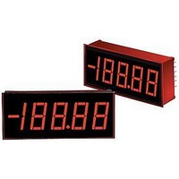
DC Miniature Digital Voltage Meter
Manufacturer
Murata Power Solutions Inc
Datasheet
1.DMS-40PC-3-RS-C.pdf
(6 pages)
Specifications of DMS-40PC-3-RS-C
No. Of Digits / Alpha
4-1/2
Meter Function
DC Voltmeter
Meter Range
± 0V To ± 200V
Digit Height
13.2mm
Power Consumption
500mW
Operating Temperature Range
0°C To +50°C
Accuracy
±2
Display Type
4 - 1/2 Digit LED
Sample Rate
2.5 SPS
Rohs Compliant
Yes
Lead Free Status / RoHS Status
Lead free / RoHS Compliant


Performance/Functional Specifi cations
Typical at T
circuit, unless otherwise noted.
Analog Inputs
Full Scale Input Range:
Input Impedence:
Overvoltage Protection ➀
Common Mode Voltage Range
CMRR (dc to 60Hz)
Control Inputs ➁
Decimal Pt. Placement (Pins 4-6, 8)
Display Test (Pin 2)
Display Hold (Pin 9)
BCD Outputs ➂
Logic Levels (1 LSTTL load max.):
Performance
Sampling Rate
Accuracy (3 minute warm-up):
Zero Reading (Vin = 0 Volts)
Temperature Drift (0 = +50°C)
Power Supply Requirements
Supply Voltage
Supply Current:
Display
Display Type and Size
Polarity Indication
Overrange Indication
Physical/Environmental
Operating Temperature
Storage Temperature
DMS-40PC-1
DMS-40PC-2
DMS-40PC-3
DMS-40PC-1
DMS-40PC-2, -3
Logic “1”
Logic “2”
DMS-40PC-1 (Vin = +1.9V)
DMS-40PC-2 (Vin = +19V)
DMS-40PC-3 (Vin = +190V)
DMS-40PC-1
DMS-40PC-2, -3
Standard Models ➃
Low-Power Models
A
= +25°C and supply voltage = +5V using the single-ended input
+2.4
“–001”
+4.75
Min.
–20
100
Tie to pin 3 to activate all segments
0.8
"–0000" (fl ashing) for negative Vin
4½ digit, 0.52"/13.2mm high LED
Autopolarity ("–" for negative Vin)
–
–
–
–
–
–
–
–
–
–
–
–
–
0
"0000" (fl ashing) for positive Vin
Tie to pin 3 to hold last reading
–
–
2.5 reading per second
Tie to pin 3 to activate
“000”
+5.00
+100
+35
±200
1000
+0.4
±0.4
±0.4
Typ.
±20
±2
±2
±3
±3
86
1
–
–
–
–
–
+5.25
+140
+50
“001”
±250
Max.
+0.8
±1.5
+50
+75
±2
±3
±4
±4
±1
–
–
–
–
–
–
–
www.murata-ps.com/dpm
Volts
Volts
Volts
Cnts/°C
Cnts/°C
Counts
Counts
Counts
Units
Volts
Volts
Volts
Volts
Volts
MΩ
MΩ
mA
mA
dB
°C
°C
➀ Applies for transient or continuous overvoltages applied to (+) INPUT HI (pin 11) with (–)
➁ See Technical Notes.
➂ BCD outputs are optional and must be specifi ed in the part number.
➃ Includes high-intensity and BCD-output models.
TECHNICAL NOTES
1. ANALOG COMMON (Pin 10): This pin is an internal, low-noise
2. REFERENCE INPUT/OUTPUT (Pin 7): This pin accesses the meter’s
3. DISPLAY TEST (Pin 2): Connecting pin 2 to ground (pin 3, 5V
DMS-40PC - 1 - R S - C
Humidity (non-condensing)
Case Material
Weight
Ordering Information
Input Range:
INPUT LO (pin 12) properly connected. Pin 12 is not overvoltage protected (see Figure 1).
Voltages applied to pin 12 should not exceed the supply voltage.
See Ordering Information.
BCD Output Models:
Accessories:
ground for the DMS-40PC. It is internally connected to pin 3
(5V RETURN). Do not connect pin 10 to either pin 3 or your system
ground as this will create a ground loop and possibly result in errone-
ous readings.
internal reference and is used during the factory calibration proce-
dure. Pin 7 should be left open in most common applications. It can
be used in certain “ratiometric” applications in which it is desirable
for the meter’s reference to track an external reference. See Ap Note
3 in the DATEL Panel Meter Catalog for more details.
RETURN) will activate all LED segments, and the display will read
“–18888” regardless of the actual applied input. To reduce self-heat-
ing, the display should not be left in the “test” mode for more than 10
seconds. This pin should be left open if unused.
A panel-mount retaining clip is supplied with each model.
1 = ±2V
2 = ±20V
3 = ±200V
BCD outputs are only available on standard red meters.
DMS-30-CP
DMS-BZL1-C
DMS-BZL2-C
DMS-EB-C
4½ Digit, LED Display Digital Panel Voltmeters
DMS-40PC-1-RS-BCD-C for ±2V input range
DMS-40PC-2-RS-BCD-C for ±20V input range
DMS-40PC-3-RS-BCD-C for ±200V input range
DMS-40PC-1-RL-BCD-C for ±2V input range
DMS-40PC-2-RL-BCD-C for ±20V input range
DMS-40PC-3-RL-BCD-C for ±200V input range
Panel cutout punch
DMS-40 bezel assembly
DMS-40 bezel assembly with sealing gasket
Application/evaluation board with standard
MOLEX connector, decimal point solder pads
and attenuation resistor pads.
DMS-40PC Series
LED Color:
04/05/11 MPM_DMS-40PC.C05 Page 2 of 6
GS = Standard Green
RH = High-Intensity Red
RL = Low-Power Red
RS = Standard Red
YS = Standard Yellow
0
Add -C for RoHS
email: sales@murata-ps.com
0.75 ounces (21 grams)
Polycarbonate
–
95
%
Related parts for DMS-40PC-3-RS-C
Image
Part Number
Description
Manufacturer
Datasheet
Request
R

Part Number:
Description:
DPM ±2V 4.5 Dig Yel LED
Manufacturer:
Murata Power Solutions Inc
Datasheet:
Part Number:
Description:
DPM ±2V 4.5 Dig Red LED
Manufacturer:
Murata Power Solutions Inc
Datasheet:
Part Number:
Description:
DPM ±20V 4.5 Dig Red LED
Manufacturer:
Murata Power Solutions Inc
Datasheet:
Part Number:
Description:
DPM ±20V 4.5 Dig Red LED
Manufacturer:
Murata Power Solutions Inc
Datasheet:
Part Number:
Description:
DPM ±20V 4.5 Dig Red LED
Manufacturer:
Murata Power Solutions Inc
Datasheet:
Part Number:
Description:
DPM ±20V 4.5 Dig Yel LED
Manufacturer:
Murata Power Solutions Inc
Datasheet:
Part Number:
Description:
DPM ±200V 4.5 Dig Grn LED
Manufacturer:
Murata Power Solutions Inc
Datasheet:
Part Number:
Description:
DPM ±200V 4.5 Dig Red LED
Manufacturer:
Murata Power Solutions Inc
Datasheet:
Part Number:
Description:
DPM ±200V 4.5 Dig Red LED
Manufacturer:
Murata Power Solutions Inc
Datasheet:
Part Number:
Description:
DPM ±200V 4.5 Dig Red LED
Manufacturer:
Murata Power Solutions Inc
Datasheet:

Part Number:
Description:
Digital Panel Meters DMS-20 BezelAssembly Panel mount
Manufacturer:
Murata Power Solutions Inc
Datasheet:

Part Number:
Description:
DPM LED MINI 2VDC 3.5DIG LP RED
Manufacturer:
Murata Power Solutions Inc
Datasheet:

Part Number:
Description:
DPM LED 2VDC 4.5DIGIT GREEN
Manufacturer:
Murata Power Solutions Inc
Datasheet:

Part Number:
Description:
DPM LED 2VDC 3.5DIGIT LP RED
Manufacturer:
Murata Power Solutions Inc
Datasheet:

Part Number:
Description:
Transformers 5Vin 5Vout 200mA 4000Vdc 1:1.33 turn
Manufacturer:
Murata Power Solutions Inc
Datasheet: